
Reading a welding drawing without understanding AWS welding symbols is like trying to read a map in a foreign language. This guide breaks down the AWS welding symbol chart in plain terms, covering every component from the reference line to supplementary symbols. Whether you’re a student, fabricator, or inspector, you’ll walk away knowing exactly how to interpret weld symbols on engineering drawings.
An Aluminum MIG Welding Settings Chart serves as a comprehensive reference guide that outlines the appropriate wire feed, voltage, and gas settings for welding aluminum effectively. Each symbol communicates weld type, size, location, finish, and process using a reference line, arrow, and specific geometric symbols placed in defined positions.
What Is the AWS Welding Symbol Standard?
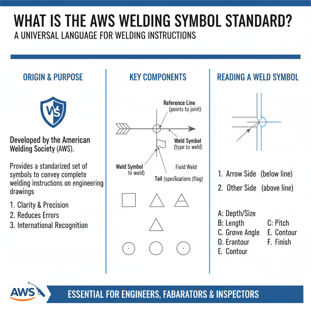
The American Welding Society (AWS) publishes standard AWS A2.4, which defines the symbols used to communicate welding requirements on engineering and fabrication drawings. This standard is used across manufacturing, construction, shipbuilding, and structural steel industries throughout the United States and internationally.
The purpose of the standard is simple: eliminate guesswork. A welder in Texas and an inspector in Ohio should read the same symbol and reach the same conclusion about what weld is required.
The Anatomy of a Complete Welding Symbol
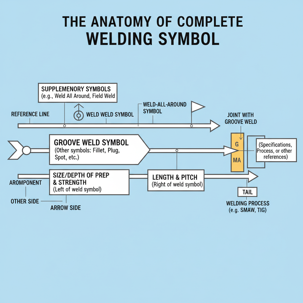
Every AWS welding symbol is built around a reference line — a horizontal line that serves as the foundation for all other information. Understanding what goes where on this line is the key to reading any weld symbol.
Here are the core components:
- Reference line — the horizontal baseline of the symbol
- Arrow — points to the joint or member being welded
- Weld symbol — the geometric shape indicating weld type (placed on or above the reference line)
- Tail — optional V-shape at the opposite end of the arrow, used for notes or process specifications
- Dimensions — numbers indicating weld size, length, and pitch
- Supplementary symbols — additional indicators for finish, contour, or field welds
The arrow side refers to the side of the joint the arrow points to. The other side is the opposite face. Symbols placed below the reference line apply to the arrow side. Symbols placed above the reference line apply to the other side.
This is one of the most commonly confused concepts for beginners. Remembering “below = arrow side” will save significant errors in the field.
Common Weld Types and Their AWS Symbols
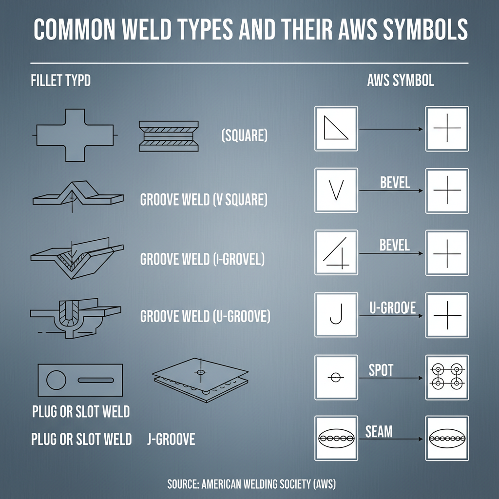
The geometric symbol placed on the reference line tells the welder what type of weld to make. Here’s a quick-reference table of the most frequently used weld symbols:
| Weld Type | Symbol Description | Common Application |
|---|---|---|
| Fillet weld | Right triangle | Lap joints, T-joints |
| Groove weld (V) | V-shape opening | Butt joints, full penetration |
| Groove weld (bevel) | Single angled line | One-sided prep joints |
| Square groove | Two parallel vertical lines | Thin material butt joints |
| Plug/slot weld | Circle or rectangle | Overlapping plates |
| Spot weld | Circle on reference line | Sheet metal, resistance welding |
| Seam weld | Circle with lines through it | Continuous sheet metal joints |
| Back/backing weld | Semicircle | Reinforcing root of groove welds |
| Surfacing weld | Flat line with wavy base | Hard-facing, buildup applications |
Fillet and groove welds account for the majority of symbols you’ll encounter in structural and fabrication work.
How to Read Dimensions on a Welding Symbol
Dimensions appear to the left and right of the weld symbol on the reference line. Their placement is specific and intentional.
Fillet weld dimensions:
- The number to the left of the symbol indicates weld size (leg length)
- The number to the right indicates weld length
- A hyphen between two numbers on the right side (e.g., 2-5) means 2-inch welds spaced 5 inches apart (intermittent weld)
Groove weld dimensions:
- The number in parentheses indicates the depth of groove preparation
- The number outside parentheses indicates the effective throat
- The angle of the groove bevel may appear inside the symbol itself
For example, a symbol showing (1/2)-5/8 next to a V-groove symbol means the groove is prepared to 1/2 inch depth with a 5/8-inch effective throat.
Supplementary Symbols Explained
Supplementary symbols add requirements beyond the basic weld type. They appear in specific positions around the reference line.
Weld-all-around symbol: A small circle at the junction of the arrow and reference line. This means the weld continues completely around the joint — common on pipe connections and structural tube columns.
Field weld symbol: A filled flag at the arrow/reference line junction. This indicates the weld must be made in the field (on-site), not in the shop.
Contour symbols: These appear above or below the weld symbol and specify the finished surface shape:
- Flat contour: a straight horizontal line
- Convex contour: a curved line arching upward
- Concave contour: a curved line arching downward
Finish method letters may accompany contour symbols:
- G = grinding
- M = machining
- C = chipping
- R = rolling
In practice, a flat contour with a G means the weld face must be ground flush. This is common in fatigue-sensitive applications or where surface appearance matters.
The Tail: Process and Specification Notes
The tail is the V-shaped fork at the end of the reference line opposite the arrow. It’s optional — when no special information is needed, the tail is omitted.
When present, the tail contains:
- Welding process designations (e.g., SMAW, GMAW, GTAW, FCAW)
- Specification references (e.g., AWS D1.1 procedure numbers)
- Special instructions that don’t fit elsewhere on the symbol
A tail reading “GTAW” tells the welder that gas tungsten arc welding is required for that joint — not just any process.
Common Mistakes When Reading AWS Weld Symbols
Even experienced welders misread symbols. These are the errors that show up most often in the field:
1. Confusing arrow side and other side
Placing a fillet on the wrong face of a T-joint is a costly mistake. Always confirm which side the arrow physically touches before welding.
2. Ignoring the weld-all-around circle
Missing this small circle means leaving sections of a joint unwelded. On pressure vessels or structural connections, that’s a serious defect.
3. Misreading intermittent weld spacing
The pitch number in an intermittent weld symbol is the center-to-center distance, not the gap between welds. Confusing these two leads to under-welding.
4. Overlooking the tail
Skipping the tail means potentially using the wrong process or missing a referenced procedure. Always check the tail when it’s present.
5. Assuming symmetry
A symbol on one side of the reference line does not automatically apply to both sides. Both sides must be explicitly shown if both require welding.
AWS Welding Symbol Chart: Quick Reference Summary
| <p> | Symbol Location | What It Means |
|---|---|---|
| Below reference line | Arrow side weld | |
| Above reference line | Other side weld | |
| Both sides of line | Weld both sides | |
| Circle at arrow junction | Weld all around | |
| Flag at arrow junction | Field weld required | |
| Number left of symbol | Weld size | |
| Number right of symbol | Weld length | |
| Parenthetical number | Groove depth | |
| Letter in tail | Process or specification | </p> |
FAQ
What does AWS A2.4 cover?
AWS A2.4 is the American Welding Society standard that defines all welding, brazing, and nondestructive examination symbols used on engineering drawings. It’s the authoritative reference for interpreting any AWS weld symbol.
What is the difference between a weld symbol and a welding symbol?
A weld symbol refers specifically to the geometric shape that identifies the weld type (like the triangle for a fillet weld). A welding symbol is the complete assembly — reference line, arrow, weld symbol, dimensions, and any supplementary information combined.
How do I know if a weld should be on both sides of a joint?
When weld symbols appear both above and below the reference line, welding is required on both sides of the joint. A symbol on only one side means only that side is welded.
What does a circle on the reference line mean?
A small circle at the intersection of the arrow and reference line is the weld-all-around symbol. It means the weld must be continuous around the entire perimeter of the joint.
Where can I find an official AWS welding symbol chart?
The official chart is published in AWS A2.4. Many welding supply companies, vocational schools, and AWS itself distribute laminated quick-reference versions. AWS also offers digital access through their website.
What does the number in parentheses next to a groove weld symbol mean?
The number in parentheses indicates the depth of groove preparation (how deep the joint is cut or beveled). The number outside the parentheses indicates the effective throat — the actual depth of weld fusion required.
Can the same joint have different weld types on each side?
Yes. A groove weld on one side and a back weld on the other is a common combination. Each side is specified independently using the above/below reference line convention.
Final Thoughts
The AWS welding symbol chart is a precise communication tool, and reading it accurately is a core skill for anyone working with fabrication drawings. The reference line, arrow, weld symbol, and supplementary elements each carry specific meaning — and misreading any one of them can result in defective welds, rework, or structural failure.
Keeping a laminated AWS A2.4 reference chart at your workstation is standard practice for good reason. When in doubt, verify the symbol against the standard before welding — not after.