
Reading a fabrication drawing and spotting a weld symbol with two numbers separated by a dash can stop a first-time builder cold. That symbol is telling you exactly where to weld, how long each bead should be, and how far apart each weld should be placed.
Those two numbers represent the length-and-pitch notation for an intermittent weld. The first number is the length of each individual weld segment. The second number is the pitch — the center-to-center distance between weld segments. Both are measured in the same unit, typically inches or millimeters. For example, a callout reading 2-6 means each weld bead is 2 inches long, repeated every 6 inches from center to center.
What Intermittent Welds Are and Why Drawings Use Them
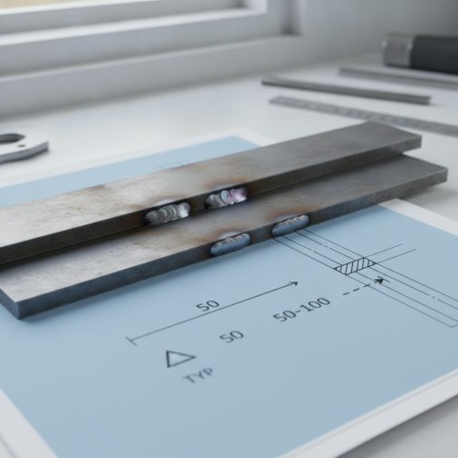
A continuous weld runs the full length of a joint without interruption. An intermittent weld — sometimes called a skip weld or stitch weld — deposits shorter beads at regular intervals along the joint instead.
Fabricators use intermittent welds for several practical reasons:
– Reducing heat input to control distortion on thin sheet metal or long structural members
– Saving filler metal and time on joints that don’t require full structural loading along their entire length
– Preventing warping on frames, brackets, gussets, and panels where excessive heat would cause the base metal to pull or bow
– Meeting design requirements where engineering calculations determine that partial welding is sufficient for the expected load
On a fabrication drawing, intermittent welds are specified using the length-and-pitch format so every welder on the job interprets the callout consistently.
How the Length and Pitch Numbers Are Written on the Symbol
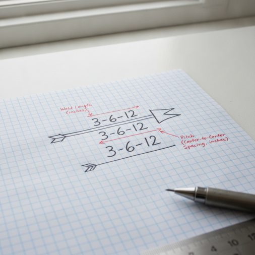
The weld symbol lives on a reference line. An arrow points to the joint being welded. The length-and-pitch values appear to the right of the weld symbol on the reference line.
The format is always:
[Weld Size] – [Length] – [Pitch]
Or when size is shown separately:
[Length] – [Pitch]
For example, a symbol showing 3/16 – 2 – 6 means:
– 3/16 in fillet weld size (leg dimension)
– 2 in weld length per segment
– 6 in pitch (center-to-center spacing)
The gap between welds — the unwelded portion — is always the pitch minus the length. In the example above, that gap is 4 inches (6 minus 2). This is a commonly misread detail. The pitch is not the gap; it’s the center-to-center distance measured from the start of one weld to the start of the next.
Reading the Symbol: Arrow Side Versus Other Side
Weld symbols follow AWS (American Welding Society) conventions. Where the weld callout sits relative to the reference line tells you which side of the joint receives the weld.
| Symbol Location | Weld Placement |
|---|---|
| Below the reference line | Arrow side of the joint |
| Above the reference line | Other side (opposite the arrow) |
| Both sides | Staggered or chain intermittent welds |
When callouts appear on both sides of the reference line, you are looking at either chain intermittent welds or staggered intermittent welds.
– Chain intermittent welds: The weld segments on both sides of the joint are directly opposite each other.
– Staggered intermittent welds: The weld segments on one side are offset halfway between the segments on the other side. Staggered welds further reduce heat concentration and distortion. On the drawing, staggered symbols are offset vertically to show this relationship.
Understanding the full weld symbol reference is worth taking seriously. If you regularly work from fabrication drawings, a proper review of AWS welding symbol standards and reference line conventions will save time and prevent misread callouts.
Units: Inches Versus Millimeters
The unit system used depends on the drawing standard and the country of origin.
– Imperial drawings express length and pitch in inches (e.g., 2–6)
– Metric drawings express them in millimeters (e.g., 50–150)
Always check the drawing’s title block for the unit system before laying out weld positions. A 50–150 callout on a metric drawing means 50 mm welds spaced 150 mm center-to-center. That same callout misread as imperial would place welds 2 inches long at 6-inch pitch — an entirely different result.
Laying Out Intermittent Welds in the Shop
Marking out intermittent welds correctly before you strike an arc prevents missing segments, incorrect spacing, and weld placement errors that require grinding and rework.
Practical layout steps:
1. Confirm the unit system on the drawing title block.
2. Identify the starting point for the first weld. Unless the drawing specifies otherwise, the first weld typically begins at the end of the joint.
3. Mark the start and end of the first weld segment using a soapstone marker or scribe.
4. Measure from the start of the first weld to the start of the next using the pitch dimension. Mark and repeat along the joint.
5. Double-check the total number of segments against the joint length before welding.
6. Tack the joint securely before running the intermittent welds to maintain fit-up and gap consistency throughout.
In practice, fabricators often mark only the start points of each segment and use a short straightedge to mark the end. Measuring only the gaps between welds instead of using center-to-center pitch is a common error that causes cumulative spacing drift along longer joints.
Weld Size in Relation to Length and Pitch
The length-and-pitch callout does not specify the weld profile. Weld size — usually the fillet leg dimension or groove depth — is shown separately on the weld symbol, typically to the left of the symbol.
If the drawing shows a fillet symbol with 1/4 to the left and 1.5–4 to the right, you have:
– A 1/4-inch fillet weld
– 1.5-inch-long segments
– 4-inch center-to-center pitch
All three dimensions carry equal importance. Ignoring the size and running oversized fillets adds unnecessary heat input and consumable cost. Running undersized fillets may not meet the required design strength.
For structural or load-bearing applications, weld size and length are engineering requirements, not suggestions. Do not substitute continuous welds for intermittent welds — or vice versa — without confirming with the engineer or a current revision of the drawing.
Common Misreads and Mistakes
Several misinterpretations appear regularly when welders and fabricators encounter length-and-pitch callouts for the first time.
Confusing pitch with gap
The pitch is center-to-center, not space between welds. Treating the pitch number as the gap results in longer unwelded spacing and shorter total weld coverage than specified.
Reading the numbers in reverse order
Length always comes first, pitch always comes second. A 2–6 callout is not the same as 6–2. The shorter number is typically the weld length.
Ignoring the tail note or weld-all-around symbol
Some drawings modify intermittent callouts with additional notes. A weld-all-around symbol (a circle at the reference line junction) means the pattern applies around the entire perimeter of the joint, not just along one face.
Applying the wrong side
Welding the wrong side of the joint because the symbol position was misread is a costly mistake. Always confirm whether the weld symbol is above or below the reference line before beginning.
Reading fabrication drawings accurately also means understanding the full notation system used on real drawings. Standard welding symbol conventions on production drawings cover the complete reference line, tail, supplementary symbols, and finish callouts that accompany weld specifications in full.
Safety While Welding Intermittent Beads
Intermittent welds are common on thin sheet metal and light structural fabrication, but the safety requirements are identical to continuous welding.
– Wear a welding helmet with a shade appropriate to your process. Shade 10 is a common starting point for MIG and stick work in the light-to-medium amperage range.
– Use flame-resistant clothing, welding gloves, and appropriate footwear regardless of weld length.
– Maintain adequate ventilation. Short welds still produce fumes, and repeated short-arc starts can actually generate localized fume concentrations in confined spaces.
– Keep combustibles clear of the weld area. Hot sparks travel the same distance whether you are running a 2-inch stitch or a continuous bead.
– Secure the workpiece to prevent shifting between weld segments. Movement during intermittent welding can misalign the joint and create gaps or mismatch at later segments.
FAQ
What does the dash between two numbers on a weld symbol mean?
The dash separates the weld length from the pitch in an intermittent weld callout. The first number is the length of each individual weld segment. The second number is the center-to-center spacing between segments. For example, a 2–6 callout means each bead is 2 inches long, placed every 6 inches on center. The gap between welds is the pitch minus the length — in this case, 4 inches.
What is the difference between chain and staggered intermittent welds?
Chain intermittent welds place segments on both sides of the joint directly opposite each other. Staggered intermittent welds offset the segments on one side so they fall between the segments on the other side. Staggered welds reduce peak heat concentration at any single cross-section and are preferred where distortion control is critical. On the drawing, staggered symbols appear offset above and below the reference line.
Is the pitch measured gap-to-gap or center-to-center?
Pitch is always center-to-center. It is measured from the starting edge of one weld segment to the starting edge of the next. Measuring gap-to-gap instead is a common mistake that shortens total weld coverage. If you need to find the gap, subtract the weld length from the pitch value.
Can I substitute a continuous weld when the drawing calls for intermittent welds?
Not without authorization. Intermittent welds are sometimes specified precisely to limit heat input and prevent distortion, particularly on thin or precision-machined components. In other cases, the engineering design may require that only specific portions of the joint carry load. Substituting a continuous weld without confirming with the engineer or drawing authority can cause both structural and dimensional problems.
Do the length and pitch numbers change when the drawing uses metric units?
The format stays the same, but the values are in millimeters instead of inches. A metric callout of 50–150 means 50 mm weld segments at 150 mm center-to-center pitch. Always verify the unit system in the drawing’s title block before laying out or welding. Mixing up metric and imperial dimensions on a callout is a significant fabrication error.
What does it mean when the intermittent weld symbol appears on both sides of the reference line?
When the callout appears both above and below the reference line, both sides of the joint receive intermittent welds. Whether those welds are chain or staggered depends on whether the symbols are aligned or offset. Aligned symbols indicate chain welds. Offset symbols indicate staggered welds. Both sides must be welded according to the dimensions shown for each side independently.
Where does weld size appear in relation to the length-and-pitch callout?
Weld size appears to the left of the weld symbol. The length-and-pitch numbers appear to the right. For a fillet weld, the size represents the leg dimension of the fillet. This distinction matters because the right-side numbers describe placement and length, while the left-side number determines the cross-sectional profile and strength of each weld segment.
Final Thoughts
The length-and-pitch callout on a weld symbol is one of the most practical pieces of information on any fabrication drawing — once you understand that pitch means center-to-center, not gap. Misreading the dash notation is one of those errors that compounds across a long joint, resulting in welds placed far off from specification. Confirm the unit system, measure from center-to-center, check which side of the reference line carries the callout, and mark out the full joint before striking the first arc.