If you’re setting up a MIG welder for the first time — or troubleshooting one that’s misbehaving — knowing what each part does makes everything click faster. A MIG welder isn’t one single machine; it’s a system of components that have to work together correctly.
A MIG welder consists of several key parts: the power source, wire feed unit, welding gun, ground clamp, shielding gas system, and consumables like the contact tip, nozzle, and liner. Each component plays a specific role in producing a stable arc and clean weld. When any single part fails or is worn out, weld quality drops noticeably.
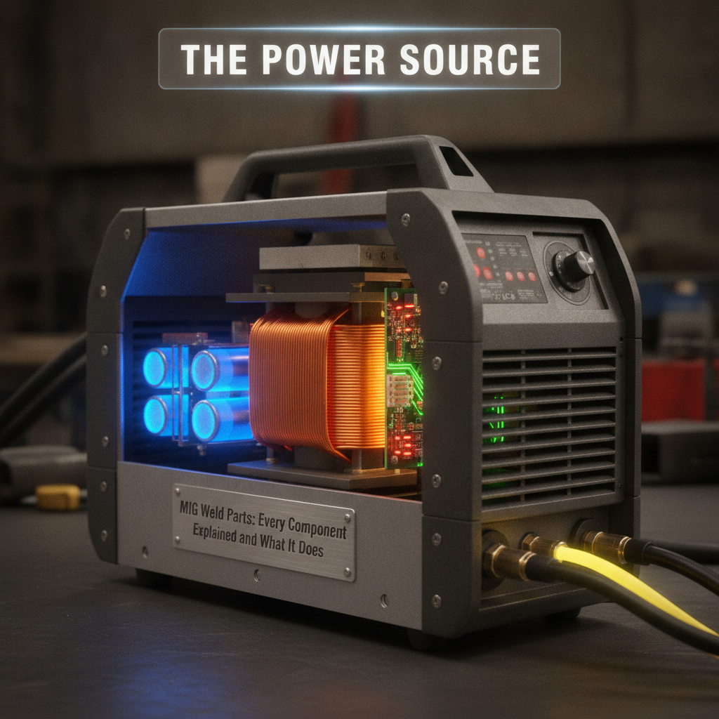
The Power Source
The power source — also called the welding machine or transformer/inverter unit — controls the voltage and amperage delivered to the arc. Most MIG welders use constant voltage (CV) output, which keeps the arc length relatively stable as wire feed speed changes.
Modern MIG machines are either transformer-based or inverter-based. Inverter machines like the Lincoln Electric Power MIG 210 MP are more compact and energy-efficient. Transformer-based machines tend to be more durable for heavy continuous use.
Voltage and wire feed speed are the two main settings you’ll adjust at the power source. These two variables control heat input and bead profile more than anything else.
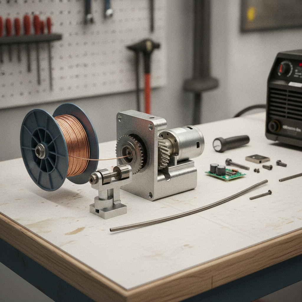
The Wire Feed Unit
The wire feed unit drives the electrode wire from the spool through the gun at a consistent speed. Feed speed is measured in inches per minute (IPM) or meters per minute (m/min), and it directly controls the amperage of the weld.
Most MIG machines have the wire feeder built into the same cabinet as the power source. On larger industrial setups, the feeder is a separate unit mounted close to the work. A dual-drive roller system grips the wire between two opposing drive rolls — one knurled, one smooth — and pushes it toward the gun.
Feed roll tension matters more than many beginners realize. Too loose and the wire slips; too tight and it gets crushed, causing bird-nesting jams. Aluminum wire requires a U-groove drive roll and lower tension because it’s soft and deforms easily.
The Welding Gun
The MIG gun is what the welder holds during operation. It delivers the wire, the welding current, and the shielding gas all to the same point simultaneously.
Inside the gun handle is a trigger switch that activates the wire feed and opens the gas solenoid at the same time. The neck connects the handle to the front consumables. Gun necks come in different angles — typically 35° to 45° — which affects access in tight joints.
The cable running from the gun back to the machine contains:
– The wire conduit (liner)
– The current-carrying copper conductor
– The gas hose
– Trigger control wires
Gun amperage rating matters. A 150A gun on a 250A machine will overheat quickly under sustained use.
Consumables: Contact Tip, Nozzle, and Liner
These three parts are the most frequently replaced components in any MIG setup. They take the most abuse, and worn consumables are one of the most common causes of frustrating weld problems.
Contact Tip
The contact tip is a small copper or copper-alloy tube that transfers welding current to the wire at the moment it exits the gun. The wire slides through the tip’s bore, and current jumps from the tip to the wire through direct contact.
Tip sizes correspond to wire diameter. A 0.030″ tip is for 0.030″ wire; using the wrong size causes erratic arc and wire stuttering.
Contact tips wear out because the wire erodes the bore over time. Signs of a worn tip include:
– Wire sticking inside the tip
– Erratic arc behavior
– Wire fusing to the tip (burnback)
Replace contact tips often. They’re inexpensive, and running a worn tip costs far more in weld quality and frustration.
Nozzle (Gas Cup)
The nozzle surrounds the contact tip and directs shielding gas over the weld pool. It’s typically made of copper or brass. Spatter builds up on the inside of the nozzle over time, which restricts gas flow and causes porosity.
Clean nozzle interiors regularly with a wire brush or pliers. Nozzle dip anti-spatter compounds help reduce buildup significantly during long weld sessions. A clogged nozzle can introduce porosity into welds even when all other settings are correct.
Gun Liner
The liner is a steel or Teflon-coated spiral tube that guides the wire from the feeder through the cable assembly to the contact tip. It’s one of the most overlooked parts on a MIG welder.
A dirty or kinked liner causes wire feed resistance, stuttering, and birdnesting jams at the drive rolls. Liners should be replaced periodically — especially if you notice wire hesitation that drive roll adjustments don’t fix.
Teflon liners are standard for aluminum wire because aluminum is soft and deposits metal residue inside steel liners quickly.
The Ground Clamp and Work Cable
The ground clamp attaches to the workpiece or welding table and completes the electrical circuit. Despite being called a “ground,” it’s actually a work return lead carrying the full welding current back to the machine.
A poor ground connection causes arc instability, spatter, and inconsistent penetration. Common problems include:
– Corroded clamp jaws
– Clamp attached to a painted or rusted surface
– Undersized work cable for the amperage being used
Always clamp as close to the weld as practical. MIG welding uses DCEP (direct current electrode positive), meaning current flows from the machine through the gun to the wire, then returns through the workpiece and ground cable.
Shielding gas protects the molten weld pool from atmospheric oxygen and nitrogen, which cause porosity and britttle welds. The gas system consists of a regulator, flow meter, solenoid valve, and hoses.
The regulator attaches to the gas cylinder and reduces high cylinder pressure down to a usable range. The flow meter (often integrated into the regulator) shows the gas flow rate, typically measured in cubic feet per hour (CFH) or liters per minute (L/min).
The correct shielding gas depends on the base metal being welded — mild steel typically uses a C25 mix (75% argon, 25% CO₂), while stainless steel requires a tri-mix or 98/2 argon/CO₂ blend.
The solenoid valve is an electrically operated valve inside the welder that opens and closes the gas flow when you pull the trigger. A sticking solenoid causes delayed gas coverage and porosity at the start of the weld.
The Wire Spool and Drive System
Wire spools come in two common sizes for shop use: 4-inch (1 lb) and 8-inch (10 lb). Larger industrial machines use 12-inch spools up to 33 lbs.
The spool mounts on a spindle inside the machine. A brake or tension knob on the spindle controls how freely the spool spins. Too little resistance and the wire overruns when the feeder stops; too much resistance and the feeder motor struggles to pull wire consistently.
Common wire types and diameters:
Wire Type
Common Diameters
Typical Application
ER70S-6 (mild steel)
0.023", 0.030", 0.035"
General fabrication, auto repair
ER4043 (aluminum)
0.030", 0.035"
Aluminum body work, castings
ER308L (stainless)
0.030", 0.035"
Stainless steel welding
E71T-11 (flux core)
0.030", 0.035"
Outdoor, no gas required
Wire diameter selection depends on material thickness. Thinner wire (0.023″) works better on sheet metal, while 0.035″ handles heavier plate more efficiently. If you’re working with thin-gauge sheet, understanding how to control heat on thin metal is just as important as wire selection.
Common Parts Problems and What They Cause
Most MIG welding problems trace back to one of the consumable or mechanical parts rather than settings.
Symptom
Likely Part Failure
Wire sticking in tip
Worn contact tip bore
Porosity in weld
Clogged nozzle, gas flow issue
Wire stutter / bird-nesting
Worn liner, drive roll tension
Weak arc / poor fusion
Bad ground clamp connection
Spatter increase
Wrong tip size, worn contact tip
Irregular bead width
Inconsistent wire feed, worn liner
If you’re running into persistent issues that settings adjustments don’t fix, walking through each physical part systematically usually finds the culprit. Troubleshooting common MIG welding problems is much easier once you understand what each component controls.
What is the most commonly replaced part on a MIG welder?
Contact tips are replaced more often than any other MIG component. They wear down as the wire erodes the bore during welding. Running a worn contact tip causes arc instability, wire burnback, and inconsistent bead quality. Most welders keep a supply of contact tips on hand and replace them at the first sign of irregular wire feeding or arc behavior.
What does the MIG gun liner do, and when should it be replaced?
The liner guides the electrode wire from the drive rolls through the cable to the contact tip. Over time, it accumulates metal dust, moisture, and debris that creates drag on the wire. Replace the liner when you notice wire feed hesitation, bird-nesting jams that aren’t caused by drive roll tension, or increased wire stuttering that cleaning doesn’t resolve. Aluminum welding requires liner replacement more frequently.
Can you use a 0.030 contact tip with 0.035 wire?
No. The tip bore must match the wire diameter. Using a 0.030″ tip with 0.035″ wire causes the wire to bind inside the tip, producing erratic arc starts, wire burnback, and tip damage. Always match tip size to wire diameter exactly. Some welders step up one tip size in specific applications, but this is only done intentionally with knowledge of the trade-off.
Why does shielding gas flow rate matter so much?
Too little gas leaves the weld pool exposed, causing porosity and atmospheric contamination. Too much gas creates turbulence that pulls air into the gas envelope, causing the same problem in a different way. The correct gas flow rate for MIG welding is typically 15–25 CFH (7–12 L/min) for most indoor applications, adjusted for nozzle diameter and drafty conditions.
What causes a MIG welder nozzle to clog so fast?
Spatter is the primary cause. When voltage is too low relative to wire speed, the arc chops and produces excessive spatter that sticks to the nozzle interior. Using nozzle dip or anti-spatter spray significantly reduces buildup. Aluminum oxide deposits from aluminum welding also build up quickly. Checking and cleaning the nozzle every few minutes during heavy weld sessions prevents gas flow restriction.
What is the difference between a gas nozzle and a contact tip?
The contact tip is the inner copper tube through which the wire exits and receives welding current. The nozzle is the outer sleeve that surrounds the contact tip and shapes the shielding gas flow over the weld pool. They are separate parts with different functions — one controls current transfer, the other controls gas coverage. Both require regular inspection and replacement.
Does the ground clamp location affect weld quality?
Significantly. A ground clamp placed far from the weld, on a painted surface, or on a loose connection introduces resistance into the circuit. This raises voltage drop, destabilizes the arc, and increases spatter. Always attach the clamp to bare metal as close to the weld area as possible. On frame or structural work, moving the clamp often immediately improves arc stability without touching any machine settings.
Every MIG weld part has a defined job, and they all depend on each other. A high-quality power source won’t compensate for a worn liner or clogged nozzle. Keeping consumables fresh, the ground connection clean, and the gas system operating correctly does more for consistent weld quality than most settings adjustments ever will.