
A worn contact tip, the wrong tip size, or a shroud packed with spatter can ruin an otherwise sound weld. If your wire keeps burning back, your arc feels unstable, or spatter is flying in every direction, the front end of your MIG gun is often the first place to investigate.
Setting up a MIG welding tip and shroud correctly means matching the contact tip bore to your wire diameter, seating the tip securely without over-tightening, and fitting the correct shroud for your gun and application. The tip should sit flush with or slightly recessed inside the shroud for most solid-wire applications. Anti-spatter compound applied to the shroud interior, and regular inspection of both components, keeps the front end running cleanly.
What the Contact Tip and Shroud Actually Do
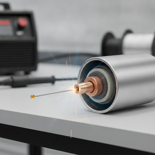
The contact tip — sometimes called a contact tube — is the small copper or copper-alloy component at the front of the MIG gun. It transfers welding current from the gun liner to the wire at the point of electrical contact. That transfer point is what creates the arc.
The shroud, also called a nozzle or gas cup, surrounds the contact tip and directs shielding gas over the weld pool. Without adequate gas coverage, oxygen and nitrogen from the surrounding air contaminate the molten metal, causing porosity and a rough, porous bead surface.
These two components work as a system. If either one is worn, blocked, or incorrectly fitted, weld quality drops quickly regardless of how well the machine settings are dialed in.
Matching the Contact Tip to Your Wire Diameter
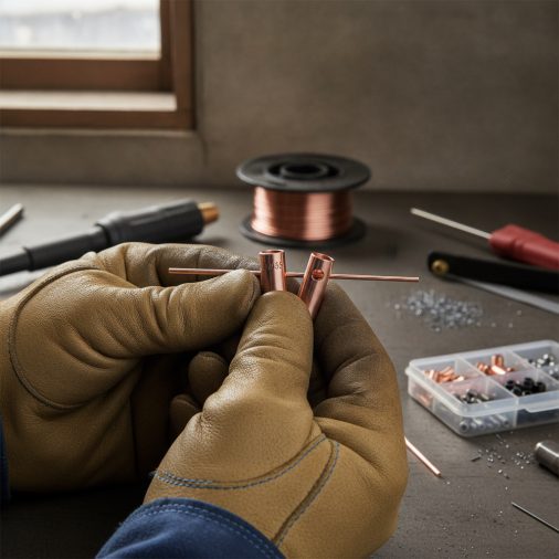
Contact tips are sized to match wire diameter, and using the wrong size is one of the most common setup mistakes. A tip that is too loose allows the wire to wander inside the bore, reducing arc stability and increasing spatter. A tip that is too tight can restrict wire feeding and cause burnbacks.
Standard contact tip bore sizes align with common wire diameters:
| Wire Diameter | Contact Tip Bore (Approx.) |
|---|---|
| 0.6 mm (0.023 in) | 0.7 mm (0.028 in) |
| 0.8 mm (0.030 in) | 0.9 mm (0.035 in) |
| 0.9 mm (0.035 in) | 1.0 mm (0.040 in) |
| 1.0 mm (0.040 in) | 1.1 mm (0.045 in) |
| 1.2 mm (0.045 in) | 1.3 mm (0.052 in) |
These are nominal values. Always check the contact tip packaging or your gun manufacturer’s consumables list for the exact specification. Not all tips labelled for the same wire diameter are interchangeable across different gun brands — thread pitch and tip length vary between manufacturers, and MIG welding tips are not universally interchangeable even when they appear similar in size.
How to Install the Contact Tip
Before handling any part of the front end, switch the welder off and release any pressure on the wire feed by releasing the drive roll tension. The tip and shroud get extremely hot during welding — allow adequate cooling time before touching them with bare hands.
1. Remove the shroud by unscrewing it or pulling it free depending on whether it is a threaded or push-on design.
2. Unscrew the worn contact tip counterclockwise. If it is seized from heat and spatter, use a pair of long-nose pliers — never grip it with sharp-jaw pliers that could damage the threads.
3. Inspect the tip bore for elongation, narrowing, or spatter buildup. A worn tip bore no longer looks circular — it becomes oval or grooved from wire friction and arc erosion. Replace it rather than attempting to clean it.
4. Thread the new tip in by hand first, then snug it with pliers. Finger-tight is not enough — a loose tip creates resistance and arcing at the tip-to-diffuser interface. Overtightening risks cracking the tip or seizing the threads when the tip heats up.
5. Refit the shroud and confirm it seats fully without cross-threading.
Feed a short length of wire through the gun and confirm it exits smoothly through the tip. If it catches, hesitates, or requires force, recheck the tip bore size and liner condition.
Tip Setback: Flush, Recessed, or Extended?
Tip position relative to the shroud opening affects arc behaviour, gas coverage, and spatter accumulation.
For solid-wire MIG welding (the most common setup), the contact tip should sit slightly recessed — approximately 1–3 mm back from the shroud opening. This positions the arc slightly deeper inside the gas envelope, improving shielding coverage and reducing spatter adhesion on the tip face.
For flux-core welding (FCAW), the contact tip is often run flush with the shroud or slightly extended. Flux-core wire generates its own shielding from the flux, so precise gas coverage geometry matters less. The extended tip position helps maintain consistent electrical stickout.
For aluminium MIG welding, a slightly more extended tip position can help compensate for the softer wire and higher feed speed required, but tip setback guidance from your gun manufacturer should take priority.
Adjustable-setback tips are available for some gun models, allowing you to set the recess position without changing the physical tip.
Shroud Selection and Fitting
Shrouds come in several configurations. The right choice depends on your gun amperage rating, the material, and the access requirements of the joint.
– Cylindrical shrouds are standard for most flat and horizontal welding. They provide even gas coverage across a wide arc.
– Tapered or conical shrouds give better visibility of the weld pool and are useful for tight joints, fillet welds, and welding in corners.
– Insulted shrouds have a non-conductive coating that reduces the chance of the nozzle short-circuiting against the base metal when working in tight spaces.
– Heavy-duty copper shrouds handle higher heat loads on higher-amperage machines and last longer in continuous production environments.
Shroud diameter should match your gun’s diffuser. An incorrectly sized shroud won’t seat properly and will allow atmospheric contamination at the joint between the shroud and diffuser body.
When fitting the shroud, push-on types should seat fully onto the diffuser without gaps. Threaded shrouds should be snugged down without forcing — damaged threads on the diffuser body are a common and unnecessary repair.
Anti-Spatter and Cleaning the Shroud
Spatter accumulates inside the shroud during welding and eventually restricts gas flow. Restricted gas flow leads directly to porosity — a problem that looks like machine settings or technique but is actually a maintenance issue.
Applying an anti-spatter compound to the inside of the shroud before welding significantly reduces spatter adhesion. Water-based anti-spatter sprays or dips — such as the Escoo Anti-Spatter Spray — are widely used and are preferred over solvent-based types because they leave no residue that could contaminate the weld zone.
To clean a shroud that has accumulated spatter:
1. Remove the shroud from the gun.
2. Use MIG pliers or a dedicated nozzle reamer to scrape or ream the spatter free from the interior.
3. Avoid using a hammer or chisel on copper shrouds — impact damage deforms the bore and affects gas flow geometry.
4. Inspect the shroud for burn-through or cracks. A compromised shroud cannot maintain consistent gas coverage and should be replaced.
Clean the shroud regularly rather than waiting until gas coverage fails noticeably. For high-volume work, a nozzle reaming station keeps the front end maintained without interrupting production.
Stickout and Its Relationship to Tip Condition
Electrical stickout — the length of wire between the contact tip exit and the arc — directly affects heat input and arc stability. Most MIG applications use a stickout of approximately 10–15 mm (3/8 to 5/8 inch) for solid wire, though this varies with wire diameter, amperage, and welding position.
A worn contact tip contributes to inconsistent stickout because the arc wanders across the elongated bore rather than maintaining a fixed exit point. This produces an erratic arc, uneven bead width, and increased spatter. If your arc sounds rough and crackly despite correct machine settings, a worn tip is worth checking before adjusting voltage or wire-feed speed.
For a full setup reference including wire-feed speed, voltage, and polarity settings, the complete process of setting up a MIG welder step-by-step covers these variables in detail.
PPE and Safety When Servicing the Front End
Even routine tip and shroud maintenance carries hazards worth acknowledging.
– Allow the gun to cool fully before touching any front-end components — contact tips and shrouds reach temperatures well beyond safe handling after even a short welding session.
– Wear safety glasses when reaming spatter from a shroud. Spatter fragments can eject unpredictably.
– Confirm the machine is switched off and the wire-feed drive rolls are disengaged before threading a new tip or pulling wire through manually.
– Inspect the gun cable and liner for wear during any front-end service — a deteriorating liner causes feeding problems that no amount of tip replacement will fix.
– When welding resumes after maintenance, verify shielding gas flow at the correct rate before striking an arc. Gas flow rates for different applications are covered in detail if you need to confirm the right litres per minute for MIG welding.
Troubleshooting Front-End Problems
| Symptom | Likely Cause | What to Check | Fix |
|---|---|---|---|
| Wire burnback into tip | Tip bore clogged or wire speed too low | Inspect tip bore; check wire-feed speed | Replace tip; adjust feed speed |
| Excessive spatter | Worn tip, wrong tip size, gas restriction | Tip bore, shroud blockage, gas flow rate | Replace tip; clean shroud; check gas |
| Porous weld beads | Blocked shroud reducing gas coverage | Shroud interior; gas flow at the diffuser | Clean or replace shroud; verify gas flow |
| Erratic or wandering arc | Elongated or worn tip bore | Inspect tip bore for oval wear pattern | Replace contact tip |
| Wire feeding roughly | Tip bore too tight or liner worn | Compare tip bore to wire diameter; check liner | Replace tip with correct size; inspect liner |
| Tip seizing when hot | Overtightened during installation | Thread contact and torque at installation | Snug firmly, not aggressively; use anti-seize on threads |
Work through one variable at a time. Replacing the tip, cleaning the shroud, and adjusting gas flow simultaneously makes it difficult to identify which factor was actually causing the problem.
FAQ
How often should I replace the contact tip on my MIG gun?
Replace the contact tip when the bore shows visible elongation, when wire feeding becomes inconsistent, or when the arc starts to sound rough despite correct machine settings. For light hobby work, a single tip may last several sessions. In production environments, tips may need replacing every few hours of arc time. Inspect the bore after every extended welding session rather than waiting for obvious failure.
Can I use the same contact tip for different wire diameters?
No. Each contact tip is sized to a specific wire diameter. Running a 0.8 mm wire through a tip bored for 0.9 mm wire causes arc wandering, inconsistent fusion, and increased spatter. Running a wire that is too large for the bore causes feeding resistance and potential burnback. Always match the tip to the wire diameter currently loaded in the machine.
Why does my contact tip keep burning back even with correct wire-feed speed?
Burnback is usually caused by insufficient wire-feed speed, holding the gun too far from the workpiece, a partial obstruction in the tip bore, or a worn liner restricting smooth wire delivery. Check that the stickout distance is within the recommended range — typically 10–15 mm for solid wire — and inspect the tip bore and liner for wear or blockage before adjusting the wire-feed speed further.
Does tip position inside the shroud affect shielding gas coverage?
Yes. A tip that protrudes too far beyond the shroud opening exposes the arc to more atmospheric air, reducing the effectiveness of the shielding gas envelope. Recessing the tip 1–3 mm inside the shroud keeps the arc deeper within the gas coverage zone. For flux-core welding, where shielding comes primarily from the flux rather than the gas, tip setback rules are more relaxed.
What causes spatter to build up inside the shroud so quickly?
Spatter buildup accelerates when voltage is set too low relative to wire-feed speed, when the gun angle is too steep, or when the arc is being held too close to the base metal. Incorrect polarity — such as running solid wire on DCEN rather than DCEP — also generates excessive spatter. Address the root cause rather than relying solely on more frequent shroud cleaning. Check that MIG welding polarity is set correctly for the wire type in use.
Is there a difference between a shroud and a nozzle?
The terms are used interchangeably in most workshop and retail contexts. Some manufacturers distinguish between a nozzle as the outermost gas-directing component and a shroud as the full assembly including the diffuser body, but in general use, both terms refer to the cylindrical or tapered gas-directing component that surrounds the contact tip. Check your gun’s parts diagram to identify the exact component names for your specific model.
Can anti-spatter spray damage the contact tip or weld quality?
Water-based anti-spatter products are generally safe for use on the shroud interior and will not contaminate the weld when applied correctly. Avoid applying anti-spatter directly to the contact tip face or the base metal within the weld zone, as residue can affect arc initiation and potentially introduce contamination. Apply it only to the inner shroud surface, and allow a moment for any excess to drain before welding.
Keep the Front End Maintained and the Rest Follows
The contact tip and shroud are small, inexpensive components, but their condition has a disproportionate effect on weld quality. A correctly sized, properly seated tip and a clean shroud with unrestricted gas flow solve a significant share of the arc instability, spatter, and porosity problems that welders often attribute to machine settings or technique. Replace tips at the first sign of bore wear, clean the shroud before blockage affects gas coverage, and confirm tip setback and stickout are appropriate for the wire type and application. Getting these details right makes the rest of the setup far more predictable.