
Why Travel Speed Affects Weld Quality More Than Most Welders Realize
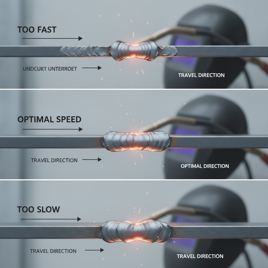
MIG Welding Travel Speed Chart by Material Thickness

| Material Thickness | Wire Diameter | Voltage (V) | Wire Feed Speed (IPM) | Travel Speed (IPM) |
|---|---|---|---|---|
| 18 gauge (0.048") | 0.023" | 14–16 | 150–180 | 22–30 |
| 16 gauge (0.060") | 0.023"–0.030" | 15–17 | 170–200 | 20–28 |
| 14 gauge (0.075") | 0.030" | 16–18 | 190–230 | 18–25 |
| 3/16" (0.188") | 0.030"–0.035" | 18–20 | 220–260 | 15–22 |
| 1/4" (0.250") | 0.035" | 19–22 | 240–280 | 12–18 |
| 3/8" (0.375") | 0.035" | 21–24 | 280–340 | 10–16 |
| 1/2" (0.500") | 0.035"–0.045" | 23–26 | 320–400 | 10–14 |
What Good vs. Bad Travel Speed Looks Like
Learning to read your bead is the fastest way to correct travel speed problems. Here’s what to look for: Signs of too-fast travel speed: – Narrow, stringy bead – Undercut along the toes of the weld – Poor fusion or incomplete penetration – Bead appears raised with steep edges Signs of too-slow travel speed: – Wide, flat, or convex bead – Excessive spatter – Burn-through or distortion on thin material – Weld pools forward of the arc (you’re outrunning the puddle) Signs of correct travel speed: – Consistent bead width roughly 2–3 times the wire diameter – Smooth, slightly convex profile – Even ripple pattern along the bead – Clean toes with no undercut In practice, a properly set travel speed produces a bead that looks like a consistent rope of weld with uniform width throughout.How Travel Speed Relates to Other MIG Settings
Travel speed doesn’t work in isolation. It’s connected to your voltage, wire feed speed and voltage settings, and the deposition rate of your wire. Think of it this way: voltage controls arc energy and bead profile, wire feed speed controls deposition rate, and travel speed controls how much of that deposited metal gets spread over each inch of joint. If you increase wire feed speed without adjusting travel speed, the bead gets taller and wider. If you increase voltage without slowing down slightly, you may get a flatter bead with more spatter. The relationship that matters most is heat input per unit length: Heat Input (kJ/in) = (Volts × Amps × 60) ÷ (Travel Speed in IPM × 1000) This formula becomes particularly important on stainless steel and heat-sensitive alloys where controlling heat input directly affects mechanical properties and distortion.Travel Speed Adjustments by Welding Position
Flat position gives you the most control and allows for a full range of travel speeds. Other positions require modification. Vertical-up welding: – Reduce travel speed by 20–30% – Let gravity help fill the joint rather than fighting it – Use a weave or zigzag pattern to control the puddle Vertical-down welding: – Increase travel speed by 15–25% – Suitable for thin sheet metal – Not recommended for thick plate due to poor penetration Overhead welding: – Use slightly faster travel speed to prevent puddle sag – Reduce voltage slightly and increase wire feed speed to compensate – Smaller puddle = better overhead control Horizontal welding: – Moderate travel speed similar to flat, but slightly faster to prevent sag – Angle the gun slightly upward (10–15°) to support the puddleTravel Speed for Different MIG Wire Types
Wire type and shielding gas also influence where your ideal travel speed falls. Solid wire with C25 (75/25 Ar/CO₂): Standard reference point. All chart values above apply directly. Solid wire with 100% CO₂: CO₂ runs hotter and more penetrating. You may need to increase travel speed slightly (5–10%) to prevent excessive buildup and burn-through on thin material. Flux core wire (FCAW): Flux core runs at higher deposition rates. Travel speeds tend to be slightly faster to manage the larger puddle. If you’re dialing in flux core MIG welding settings, expect to push your speed toward the higher end of the range for a given thickness. Gasless flux core: Similar to standard flux core but pay close attention to bead width. Gasless wire produces more spatter and a larger heat-affected zone, which makes travel speed control even more critical.Practical Tips for Dialing In Travel Speed
Run a test bead first. Always run a short test pass on scrap material of the same thickness before welding the actual part. Measure the bead width — it should be consistent and proportional to the joint width. Watch the puddle, not the arc. Experienced welders track the trailing edge of the puddle, not the arc itself. If the puddle grows larger as you move, slow down. If it gets smaller and the arc seems to be chasing the metal, speed up. Maintain consistent gun angle. A drag angle of 5–15° (pushing or dragging depending on technique) keeps the travel speed consistent. Varying your angle mid-pass effectively changes your travel speed and heat input. Mark your travel rate on practice pieces. Some welders use a sharpie to draw 1-inch marks on practice plate, then count seconds per inch to establish a consistent pace. At 15 IPM, you should be moving approximately 1 inch every 4 seconds. Use a consistent body position. Travel speed inconsistency often comes from awkward body mechanics. Position yourself so you can complete the entire weld joint with a smooth, uninterrupted arm movement. Welders working on projects like MIG welding square tubing frames often benefit from practicing consistent travel speed on long, straight runs before tackling corners and short tacks.Common Travel Speed Mistakes and How to Fix Them
Inconsistent speed along the joint: This creates a bead that’s wider in some spots and narrower in others. Usually caused by uncomfortable welding position or stopping and restarting mid-bead. Fix: reposition yourself before starting, and practice the motion without the trigger first. Speeding up at the end of a bead: A very common habit. As your arm reaches the end of its natural movement range, it tends to accelerate. This leaves a thin, undercut tail on the weld. Fix: slow deliberately as you approach the end of the joint. Slowing down on tacks or starts: The opposite problem — welders often hesitate at the beginning of a bead, depositing too much metal at the start. Fix: establish your travel pace before pulling the trigger, and start moving immediately as the arc strikes. Not adjusting for vertical or overhead positions: Using flat-position travel speeds in vertical or overhead work is one of the most common FCAW and MIG defects in the field. The puddle behaves differently, and the speed must change accordingly.FAQ
What is the ideal travel speed for MIG welding 1/4-inch steel? For 1/4-inch mild steel using 0.035″ solid wire with C25 shielding gas, a travel speed between 12 and 18 IPM is generally the right starting range. At this thickness, proper fusion requires enough dwell time for the arc to penetrate the base metal, so avoid pushing above 18 IPM without verifying penetration on a cross-section test piece. Does travel speed affect penetration depth in MIG welding? Yes, significantly. Slower travel speed increases heat input per inch, which deepens penetration and widens the heat-affected zone. Faster travel speed reduces heat input, resulting in shallower penetration and a narrower bead. On thicker material, too-fast travel speed is one of the most common causes of lack-of-fusion defects that don’t appear until the weld is destructively tested. How do I measure my MIG welding travel speed? Mark 1-inch increments on your test plate with a marker, then time how long it takes to weld across them. Divide inches by time in minutes. For example, 6 inches in 24 seconds equals 15 IPM. Alternatively, some modern wire feeders like the Lincoln Electric Power MIG 210 MP display real-time arc data that can help you correlate settings with your actual performance. Should I push or pull the MIG gun, and does it affect travel speed? Pushing (forehand technique) produces a wider, flatter bead with slightly less penetration, while pulling (backhand/drag technique) produces a narrower, deeper bead. Neither technique dramatically changes the optimal travel speed range, but pushing tends to feel more natural for maintaining consistent speed because you can see the joint ahead. Most MIG welding settings charts are based on a neutral or slight push angle. Does travel speed matter the same way for aluminum MIG welding? Aluminum requires faster travel speeds than steel due to its high thermal conductivity and lower melting point. Moving too slowly on aluminum causes burn-through almost immediately. For typical aluminum MIG applications, expect travel speeds in the 18–35 IPM range depending on thickness. Refer to dedicated aluminum MIG welding settings for material-specific guidance, since aluminum behaves very differently from mild steel. Why does my weld bead look good on the surface but fail a bend test? This is typically a travel speed problem combined with insufficient voltage. High travel speed can create a bead that looks acceptable from the outside but lacks proper fusion at the root of the joint. Always verify penetration on scrap material by cutting, grinding, and etching or bending a cross-section before trusting the surface appearance alone. How does travel speed change for multi-pass welds? On the root pass, use a moderate travel speed to ensure full penetration. Fill passes can use slightly faster speeds since the goal shifts from root fusion to filling the joint efficiently. Cap passes often use faster travel with a weave to blend smoothly into the base metal. Maintaining consistent travel speed across each pass in the same sequence gives the most uniform results.Travel speed is one of those variables that separates welders who get consistent results from those who are always chasing problems with voltage and wire speed. Once you can maintain a steady, controlled pace and read the puddle accurately, most other MIG setting adjustments become much more intuitive. Use the chart as your starting point, but let the bead tell you what to adjust.