
MIG welding is one of the most widely used welding processes in the world — from auto body repair to structural fabrication. If you’re new to it or trying to sharpen your technique, understanding how the process actually works makes everything else easier.
MIG welding (Metal Inert Gas welding) is a semi-automatic arc welding process where a continuously fed wire electrode melts into the base metal to form a weld joint. A shielding gas — typically a mix of argon and CO₂ — protects the molten pool from atmospheric contamination. The welder controls travel speed, angle, and positioning while the machine feeds wire and regulates voltage automatically.
How the MIG Welding Process Actually Works
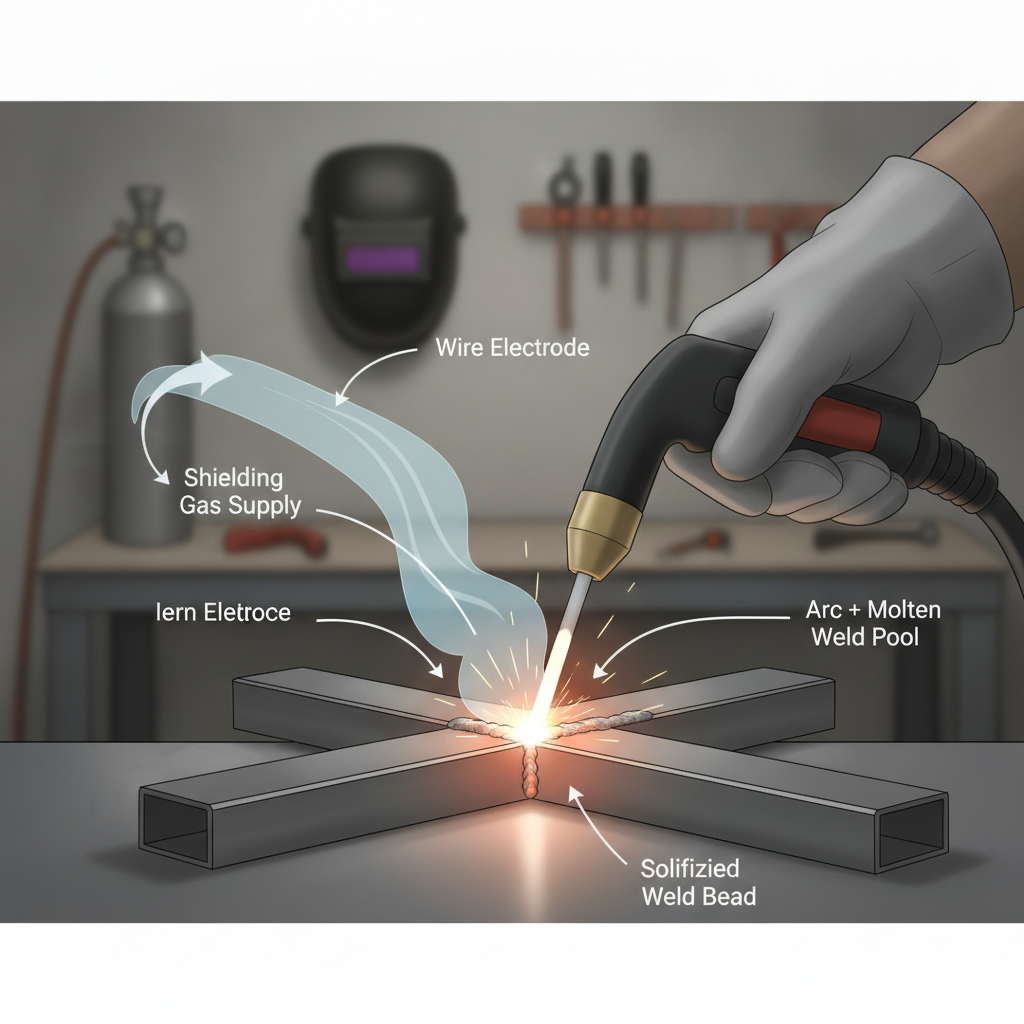
At its core, MIG welding creates an electric arc between the wire electrode and the workpiece. That arc generates intense heat — typically between 6,000°F and 10,000°F — which melts both the wire and the base metal to form a molten weld pool.
As the pool cools, it solidifies into a solid weld bead that fuses the two pieces of metal together. The entire process happens rapidly, which is why MIG is valued for speed and efficiency.
The wire electrode is fed continuously from a spool inside the welder through a liner and out the gun tip. You pull the trigger, the arc starts, and the wire feeds automatically as you move the gun along the joint.
Key Components of a MIG Welding Setup
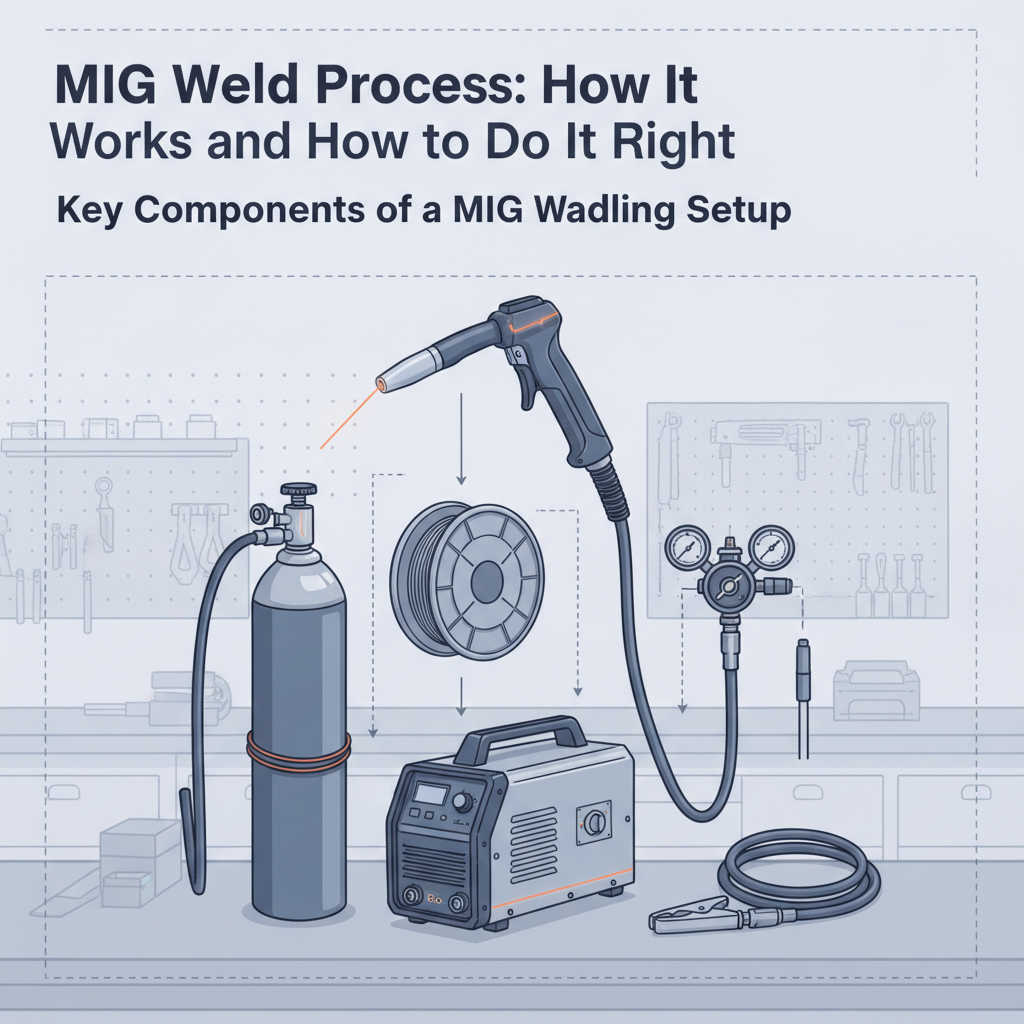
Understanding the equipment involved helps you troubleshoot problems and set up the machine correctly.
| Component | Function |
|---|---|
| Wire spool | Supplies the consumable electrode wire |
| Wire feed drive | Controls the speed at which wire is fed |
| MIG gun / torch | Delivers wire, gas, and current to the weld |
| Contact tip | Transfers current to the wire just before the arc |
| Gas nozzle | Directs shielding gas around the weld pool |
| Gas regulator & hose | Controls shielding gas flow rate |
| Ground clamp | Completes the welding circuit |
| Power source | Provides DCEP (Direct Current Electrode Positive) output |
MIG welders typically operate on DCEP polarity, which concentrates heat at the wire tip for better penetration and arc stability. Understanding MIG welding polarity settings is especially important when switching between solid wire and flux-core wire, since flux-core often runs on DCEN.
Shielding Gas: What It Does and What to Use
Shielding gas is not optional. Without it, the molten weld pool is exposed to oxygen and nitrogen, causing porosity, spatter, and brittle welds.
The most common gas choice for mild steel is a 75% argon / 25% CO₂ blend, often called C25 or 75/25. This blend gives you good arc stability, lower spatter, and a clean bead profile. Pure CO₂ is cheaper and increases penetration, but it produces more spatter.
For stainless steel, most welders use a tri-mix gas (helium, argon, CO₂) or a 98% argon / 2% CO₂ blend to prevent carbide precipitation and oxidation. Aluminum requires 100% argon.
A common flow rate for most indoor MIG welding situations is 15–25 liters per minute. Getting your shielding gas flow rate right matters more than many beginners realize — too little causes porosity, too much causes turbulence that pulls in ambient air.
Wire Electrode Types and Sizes
The wire you choose affects penetration, bead appearance, and how well the weld handles contaminated or rusty base metal.
Common wire types:
- ER70S-6 — The most widely used solid MIG wire. Works on clean and slightly rusty mild steel. The silicon and manganese deoxidizers help it handle surface imperfections.
- ER70S-3 — Cleaner base metal required. Lower deoxidizer content.
- E71T-11 (flux-core) — Self-shielded flux-core wire. No gas required. Good for outdoor work and thicker material.
- ER308L — Standard solid wire for 304 stainless steel.
- ER4043 / ER5356 — Aluminum MIG wire, used with a spool gun.
Wire diameter typically ranges from 0.023″ to 0.045″ for most shop applications. Thinner wire (0.023″–0.030″) is better for thin metal to reduce heat input, while 0.035″ is a reliable all-purpose size for 18-gauge up to about 1/4″ steel.
MIG Welding Settings: Voltage, Wire Speed, and Heat
Getting your settings right is where most beginners struggle. MIG machines have two main adjustable parameters: voltage and wire feed speed (WFS). These two variables are interdependent.
- Voltage controls the arc length and bead profile. Higher voltage produces a flatter, wider bead with more spatter. Lower voltage makes a narrow, ropy bead.
- Wire feed speed controls amperage. Faster wire feed = more heat input = deeper penetration.
A general starting point for 0.035″ ER70S-6 wire on 1/8″ mild steel:
| Parameter | Typical Starting Range |
|---|---|
| Voltage | 17–19V |
| Wire Feed Speed | 200–250 IPM |
| Shielding Gas Flow | 20 CFH (approx. 9.4 LPM) |
| Contact Tip to Work Distance | 3/8″ – 1/2″ |
Most mid-range machines include a settings chart inside the wire compartment door. The Lincoln Electric PRO MIG 180T, for example, has a built-in reference chart that maps material thickness to voltage and wire speed settings — which makes initial setup significantly faster on unfamiliar material.
Always make test welds on scrap before welding the actual workpiece. Tune voltage and WFS together until you hear a consistent frying-bacon sound, which indicates a stable arc.
Technique: Gun Angle, Travel Speed, and Direction
Even with perfect settings, poor technique will produce weak or inconsistent welds.
Gun angle:
- Hold the gun at a 10–15° drag angle (pushing the gun away from you) for most flat and horizontal welds.
- For vertical or overhead positions, a slight push angle can help control the puddle.
Travel speed:
- Move too fast and you get a narrow, undercut bead with poor fusion.
- Move too slow and the heat builds up, causing burn-through or excessive reinforcement.
- A consistent travel speed produces an even, slightly convex bead with defined ripples.
Stringer vs. weave:
- Stringer beads (straight travel, no oscillation) are stronger and preferred for most structural applications.
- Weave patterns are useful for filling wide gaps or covering a wider area in a single pass.
For thin sheet metal work, controlling heat when MIG welding thin metal often means using stitch welding instead of a continuous bead — small tack welds spaced along the joint allow heat to dissipate between passes.
Common MIG Welding Problems and Fixes
| Problem | Likely Cause | Fix |
|---|---|---|
| Porosity (small holes in bead) | Gas coverage failure, surface contamination | Check gas flow, clean base metal |
| Excessive spatter | Voltage too low, poor gas mix, long CTWD | Increase voltage slightly, verify gas |
| Burn-through | Heat too high for material thickness | Reduce WFS, use shorter bursts |
| Wire bird-nesting | Drive roll tension wrong, kinked liner | Adjust drive roll, replace liner |
| Cold lap / lack of fusion | Travel speed too fast, voltage too low | Slow down, increase voltage |
| Inconsistent bead | Unstable hand movement | Practice on flat plate first |
A common issue many welders encounter in the field is contaminated base metal. Rust, mill scale, paint, or oil will degrade shielding and introduce hydrogen into the weld pool. Always grind or clean the joint area before welding.
Where MIG Welding Is Used
MIG welding is suitable for a wide range of materials and applications:
- Mild steel — Most common application. Structural work, frames, brackets, trailers.
- Stainless steel — Food-grade fabrication, automotive exhaust, chemical equipment. Requires proper gas and wire selection. If you’re working on exhaust systems, MIG welding thin exhaust pipe requires careful heat control due to the thin-gauge tubing involved.
- Aluminum — Possible with a spool gun and 100% argon. More challenging than steel due to thermal conductivity.
- Automotive sheet metal — Body panels, floor pans, patch panels. Low heat input is essential.
MIG is generally not the best choice for very thick material (over 1/2″) without preheat and multi-pass strategy, or for outdoor welding in windy conditions where shielding gas gets blown away.
FAQ
What is the MIG welding process in simple terms?
MIG welding joins metals by melting a continuously fed wire electrode with an electric arc. The wire acts as both the electrode and the filler metal. A shielding gas flows around the weld to prevent contamination from air. The welder guides the gun along the joint while the machine handles wire feeding and arc generation automatically. It’s one of the most beginner-accessible welding processes available.
What materials can you MIG weld?
MIG welding works well on mild steel, stainless steel, and aluminum. It can also be used on some nickel alloys and certain other metals with the right wire and gas combinations. It is not suitable for cast iron, titanium, or magnesium in most shop environments. Each material requires specific wire and shielding gas, so matching those variables to the base metal is essential before starting.
What shielding gas is best for MIG welding mild steel?
The industry standard for mild steel MIG welding is 75% argon / 25% CO₂ (C25 blend). This combination provides stable arc characteristics, minimal spatter, and good bead appearance. Pure CO₂ (C100) is a cheaper alternative that increases penetration but generates noticeably more spatter. For detailed guidance on gas selection by material type, the MIG welding shielding gas chart covers the full range of options.
How long does it take to get good at MIG welding?
Most beginners can produce acceptable flat-position welds within a few hours of practice. Running consistent beads in all positions — flat, horizontal, vertical, and overhead — typically takes weeks to months of regular practice. Learning to read the puddle, adjust settings on the fly, and troubleshoot problems takes longer. The learning curve is much shorter than TIG welding, which is one reason MIG is commonly recommended for beginners.
What is the difference between MIG and flux-core welding?
MIG welding uses a solid wire electrode with external shielding gas. Flux-core welding uses a hollow wire filled with flux that generates its own shielding when burned. Flux-core doesn’t require a gas bottle, making it practical for outdoor or windy conditions. However, it produces more slag, more spatter, and a rougher bead appearance compared to solid-wire MIG. Both processes use the same type of machine.
Why is my MIG weld porous?
Porosity in MIG welds usually comes from one of three sources: insufficient shielding gas coverage, a contaminated base metal surface, or drafts blowing the shielding gas away. Check that your gas flow rate is adequate, your nozzle is clean, and the base metal is free of rust, oil, or paint. A cracked or worn liner can also allow air to enter the gas stream and cause porosity even when the regulator reads correctly.
Can you MIG weld without gas?
Yes, but only with self-shielded flux-core wire (such as E71T-11). This wire generates its own shielding from the flux core and doesn’t require an external gas supply. Standard solid MIG wire cannot be used without shielding gas — the weld will be severely contaminated and structurally compromised. If you’re switching between solid wire and flux-core, you’ll also need to reverse the drive roll polarity on most machines.
MIG welding rewards consistent setup and deliberate technique more than raw strength or speed. Get your machine settings close, clean the base metal, maintain a steady hand, and listen to the arc. Those fundamentals carry further than any single trick or shortcut.