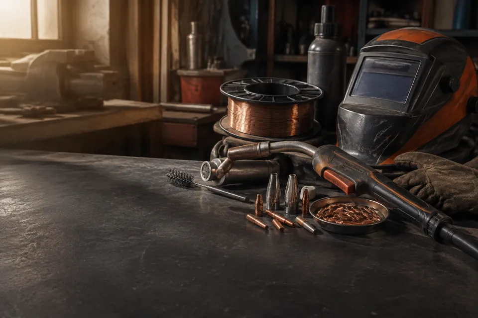
Spatter is one of the most frustrating parts of MIG welding. Those tiny balls of molten metal that land on your workpiece, your nozzle, and your welding table aren’t just annoying — they signal that something in your setup or technique isn’t quite right.
MIG weld spatter is caused by an imbalance between voltage, wire feed speed, shielding gas coverage, and arc stability. Controlling it comes down to dialing in your settings correctly, using the right gas mix, keeping your contact tip and nozzle clean, and maintaining consistent travel speed and gun angle. Most spatter problems can be fixed by adjusting voltage up slightly or wire speed down slightly, then verifying your gas flow and electrode extension.
Why MIG Welding Produces Spatter
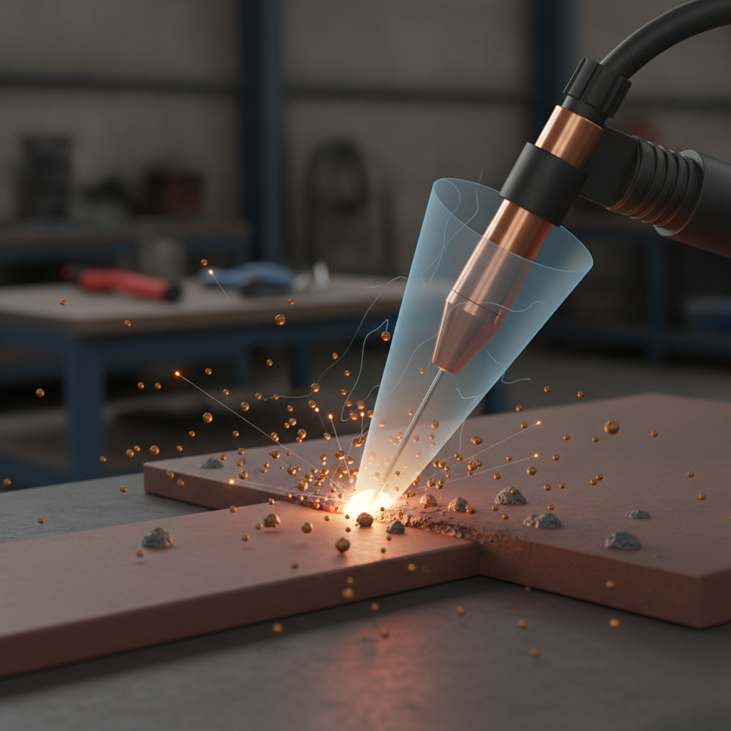
Understanding what causes spatter makes it much easier to fix.
When the arc is unstable — either too cold, too hot, or poorly shielded — molten metal gets expelled from the weld pool instead of flowing smoothly. Those expelled droplets land around the weld as spatter.
The main causes fall into a few categories:
- Voltage too low — causes a stubby, erratic arc that spits metal
- Wire feed speed too high — feeds more wire than the arc can melt cleanly
- Poor shielding gas coverage — allows atmospheric contamination to disrupt the arc
- Dirty base metal — rust, oil, mill scale, and coatings cause arc instability
- Wrong polarity — running DCEN instead of DCEP significantly increases spatter
- Excessive electrode extension (stick-out) — reduces arc stability and increases resistance
- Contaminated or damaged contact tip — disrupts current transfer and arc consistency
In practice, most spatter problems are a combination of two or three of these factors rather than a single isolated cause.
Getting Your Voltage and Wire Speed Right
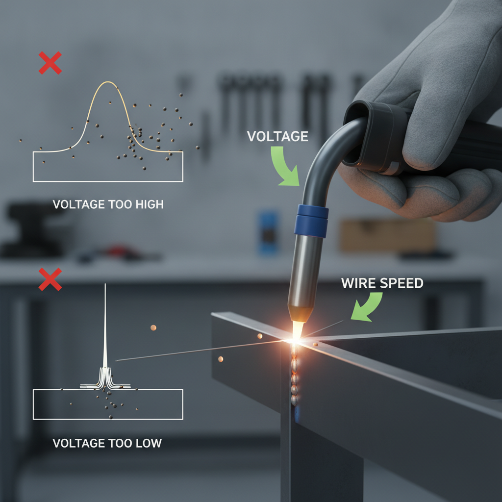
The relationship between voltage and wire feed speed is the most critical factor in spatter control.
Too little voltage makes the arc run cold and short. The wire tends to stick and ball up before being blown off, creating heavy spatter. Too much voltage opens the arc too wide, causing the puddle to go turbulent and throw spatter outward.
The goal is a smooth, consistent arc with a tight hissing or crackling sound — not popping or sputtering.
A practical approach:
- Start with the manufacturer’s settings chart for your wire diameter and material thickness
- Run a short bead on scrap metal
- Listen to the arc sound — it should hiss steadily, not pop
- If you hear popping and see heavy spatter, raise voltage slightly or reduce wire speed slightly
- Adjust in small increments (0.5V at a time) and test again
For common mild steel MIG welding with 0.030″ ER70S-6 wire and C25 gas (75% argon / 25% CO2), a stable arc typically falls between 17–22 volts depending on material thickness. Common MIG welding problems like spatter and porosity are often traced back to settings that are just slightly off from this range.
Shielding Gas Selection and Flow Rate
Shielding gas has a direct impact on spatter levels — often more than welders expect.
CO2 (100%) is the cheapest option, but it produces a more erratic arc and noticeably more spatter compared to argon-based mixes. It’s workable for structural applications where appearance isn’t critical.
C25 (75% Argon / 25% CO2) is the industry standard for mild steel MIG welding. The higher argon content stabilizes the arc and significantly reduces spatter without losing penetration.
C10 or C15 (higher argon mixes) produce even less spatter and a smoother bead profile, though they cost slightly more per cubic foot.
| Gas Mix | Spatter Level | Bead Appearance | Best For |
|---|---|---|---|
| 100% CO2 | High | Rough, wider | Structural, cost-sensitive |
| C25 (75Ar/25CO2) | Moderate-Low | Clean, smooth | General mild steel |
| C15 (85Ar/15CO2) | Low | Very clean | Sheet metal, cosmetic welds |
| 98% Ar / 2% CO2 | Very Low | Excellent | Stainless steel MIG |
Flow rate matters just as much as gas selection. Too little flow (under 15 CFH) leaves the weld pool exposed and causes porosity and spatter. Too much (over 35 CFH) creates turbulence that pulls in atmospheric air. For most applications, 20–25 CFH (approximately 9–12 liters per minute) is the right range. If you’re unsure, this breakdown of correct shielding gas flow rates for MIG welding covers the exact numbers by application.
Contact Tip, Nozzle, and Gun Maintenance
A dirty or worn contact tip is one of the most overlooked causes of chronic spatter. When spatter builds up inside the nozzle, it restricts gas flow and disrupts the arc. When the contact tip wears unevenly, current transfer becomes inconsistent.
Keep these habits as part of your regular routine:
- Clean the nozzle after every 15–20 minutes of welding using nozzle pliers or a scraper
- Apply anti-spatter spray or gel (such as Dynaflux Anti-Spatter Spray) to the inside of the nozzle before starting — spatter won’t bond as easily and cleanup takes seconds
- Inspect the contact tip regularly — if the orifice is elongated or if wire feed feels inconsistent, replace it
- Match contact tip diameter to wire diameter exactly — a worn or oversized tip increases arc wander
In practice, welders who skip nozzle maintenance often blame their machine or settings when the real problem is restricted gas flow caused by spatter buildup.
Electrode Extension and Gun Angle
Two technique factors that frequently go unaddressed are electrode extension (stick-out) and gun angle.
Electrode extension is the distance between the contact tip and the workpiece. For solid wire MIG welding, the standard range is 3/8″ to 5/8″ (10–15mm). Extending beyond this increases electrical resistance, heats the wire before it reaches the arc, and destabilizes the puddle — all of which increase spatter.
Gun angle affects both bead shape and spatter behavior:
- A drag (pull) angle of 5–15 degrees from vertical works best for most MIG applications
- Excessive gun angles (more than 20–25 degrees) direct heat unevenly and push the puddle in ways that increase spatter
- Keeping the gun perpendicular to the joint and consistent throughout the pass reduces spatter substantially
Travel speed also plays a role. Moving too slowly lets the puddle build up and become turbulent. Moving too quickly creates a cold, narrow bead with more arc instability.
Base Metal Preparation
No amount of setting adjustment compensates for dirty metal. Mill scale, rust, paint, galvanizing, and oil contamination all disrupt the arc and cause spatter.
Before welding:
- Grind or wire-brush the weld zone to bare, bright metal
- Wipe down with acetone to remove oil or cutting fluid
- Remove galvanized coatings from the weld area entirely — they produce spatter and hazardous fumes
- On thinner material, a light pass with a flap disc is often enough
This step is especially important when MIG welding thin metal, where the arc is already running at lower parameters and has less tolerance for surface contamination.
Anti-Spatter Products: When and How to Use Them
Anti-spatter products don’t fix the root cause of spatter, but they make cleanup dramatically faster when spatter is unavoidable — such as during tack welding, galvanized work, or high-production welding.
Anti-spatter sprays and gels coat the workpiece surface around the weld zone so that spatter lands but doesn’t bond. After welding, it wipes or brushes away cleanly.
Nozzle dip gel (like Bluemagic Anti-Spatter Gel) is applied inside the nozzle and on the contact tip area to prevent buildup during long welding sessions.
Use these as maintenance aids, not as a fix for bad settings. If you’re seeing heavy spatter even with anti-spatter products, the underlying settings or technique still need attention.
Spatter vs. Porosity: Knowing the Difference
Spatter and porosity sometimes appear together and share some root causes, but they’re different problems.
- Spatter lands around the outside of the weld bead — it’s metal that was expelled before it could fuse
- Porosity appears as holes or pits inside or on the surface of the bead — it’s caused by gas becoming trapped in the solidifying weld pool
Both can result from poor shielding gas coverage, contaminated base metal, or a turbulent arc. If you’re dealing with both at the same time, the most likely cause is inadequate gas flow, a bad seal in your gas line, or a contaminated wire spool.
FAQ
Why does my MIG welder produce so much spatter on thin metal?
Thin metal requires lower voltage and wire speed settings. Running settings that are calibrated for thicker stock on thin material creates an arc that’s too hot and erratic. Reduce voltage slightly, lower the wire feed speed, and verify your shielding gas flow is steady at 20–25 CFH. Using ER70S-6 wire on thin mild steel generally produces less spatter than ER70S-3 due to its higher deoxidizer content.
Does using 100% CO2 gas cause more spatter than a mixed gas?
Yes, noticeably. Pure CO2 produces a less stable arc compared to argon-CO2 mixes. The result is more metal expulsion and rougher bead appearance. Switching to C25 (75% argon / 25% CO2) typically reduces spatter by a meaningful amount without changing your machine settings significantly. For cosmetic work, C15 or higher-argon mixes reduce spatter even further.
How does inductance affect MIG spatter?
Inductance controls how quickly the welding current rises when the wire contacts the puddle. Higher inductance slows the current rise, giving the weld pool more time to absorb the wire before it detaches — this softens the arc and reduces spatter. Many modern inverter-based MIG welders include an inductance adjustment. Increasing it slightly is often an effective way to smooth out a spatter-prone arc without changing voltage or wire speed.
Can a worn contact tip really cause spatter problems?
Absolutely. A worn contact tip causes inconsistent electrical contact between the tip and the wire. This creates micro-interruptions in current flow, which destabilize the arc and throw spatter. If you’ve adjusted your settings and still have unexplained spatter, replacing the contact tip is one of the fastest and cheapest diagnostic steps you can take.
Why is there more spatter at the start of a weld than during the rest of the bead?
The beginning of a weld is the most spatter-prone moment because the base metal is cold and the arc hasn’t fully stabilized. A few techniques help: pre-heat the weld zone on thicker material, use a run-in tab to start the arc before reaching the actual joint, or try a brief pause at the start to let the puddle establish before moving forward.
Does wire type affect spatter levels?
Yes. ER70S-6 wire contains more silicon and manganese than ER70S-3. These deoxidizers help the wire handle surface contamination better and produce a more stable arc, which means less spatter overall. For general-purpose work on mild steel, ER70S-6 is the better choice when spatter control matters.
Is spatter a sign that my welds are structurally weak?
Not automatically, but spatter often indicates arc instability, which can point to inconsistent fusion or porosity in the weld. A bead that looks rough and heavily spattered warrants closer inspection. High spatter alone doesn’t mean the weld failed, but it should prompt you to check your settings and review the bead profile for signs of poor penetration or underfill.
Spatter control is mostly a settings and maintenance discipline. Get your voltage, wire speed, and gas flow dialed in together, keep your contact tip and nozzle in good condition, and prepare your base metal properly — and most spatter problems resolve without needing any special products or techniques. When spatter persists after addressing those factors, looking at inductance adjustment or wire type is usually the next productive step.