
Getting the right MIG weld settings is the difference between a clean, strong bead and a mess of spatter, porosity, and burn-through. Whether you’re patching sheet metal or welding thick structural steel, the settings matter more than technique alone.
MIG weld settings are determined by three main variables: voltage, wire feed speed, and shielding gas flow rate. Voltage controls penetration and bead width, wire feed speed controls amperage and deposition rate, and shielding gas flow protects the weld pool. For most mild steel applications, start with the chart inside your welder’s door, then fine-tune by listening for a steady crackling sound — similar to frying bacon — which indicates a good arc.
The Three Core Settings You Control
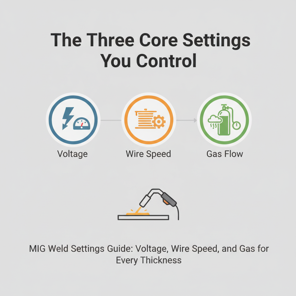
Every MIG welder gives you at least two primary adjustments: voltage and wire feed speed. Gas-shielded machines add a third — shielding gas flow rate.
These three settings are interconnected. Changing one affects the others, which is why beginners often chase their tail trying to fix one problem and creating another. Understanding what each setting actually does is the fastest way to stop guessing.
Voltage controls arc length and bead profile. Higher voltage produces a flatter, wider bead with more spatter. Lower voltage creates a taller, narrower bead that can lack fusion on thicker material.
Wire feed speed controls how much filler metal enters the weld pool per minute, which directly affects amperage. Faster wire feed means higher amperage and more heat input. Slower wire feed reduces heat and deposition.
Shielding gas flow rate doesn’t affect the arc directly, but it does protect the weld pool from oxygen and nitrogen contamination. Too little flow causes porosity. Too much causes turbulence that actually pulls in atmospheric air.
MIG Weld Settings by Material Thickness
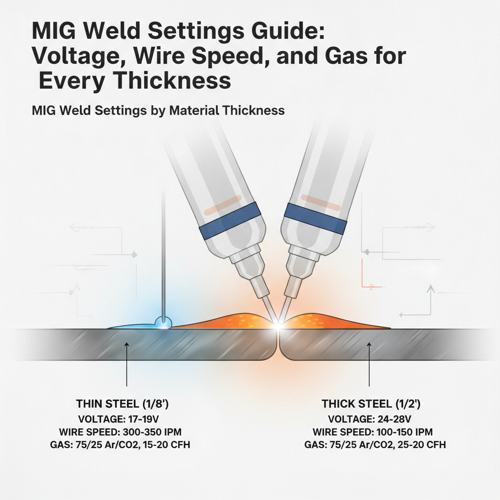
The most practical way to set up a MIG welder is by material thickness. This table covers common mild steel thicknesses using 0.030″ ER70S-6 wire and 75/25 Argon/CO₂ shielding gas.
| Material Thickness | Voltage | Wire Feed Speed | Amperage (approx.) |
|---|---|---|---|
| 24 gauge (0.024″) | 13–15V | 80–120 IPM | 30–50A |
| 18 gauge (0.048″) | 14–16V | 120–160 IPM | 50–80A |
| 16 gauge (0.060″) | 15–17V | 150–200 IPM | 75–100A |
| 1/8″ | 17–19V | 200–260 IPM | 100–140A |
| 3/16″ | 18–21V | 250–320 IPM | 130–175A |
| 1/4″ | 20–23V | 300–380 IPM | 160–210A |
| 3/8″ | 22–25V | 380–460 IPM | 200–250A |
These are starting points, not absolute values. Joint type, travel speed, and wire diameter all require adjustments. The MIG welding wire speed and voltage chart on this site goes deeper if you want a more complete reference by wire diameter and position.
Wire Diameter and When to Change It
Most hobbyist and light industrial MIG welders come loaded with 0.030″ wire, which handles a wide range of thicknesses reasonably well. But using the wrong wire diameter for the job forces you to compensate with settings that push the machine out of its efficient range.
0.023″ — Best for thin sheet metal, 22–18 gauge. Easier to control heat on automotive panels and exhaust components. Requires less amperage, which reduces burn-through risk significantly.
0.030″ — The most versatile option. Works from 18 gauge up to 3/16″ on a single-pass weld. Good balance between deposition rate and heat control.
0.035″ — Suited for 1/8″ and thicker. Higher deposition rate means faster travel speeds and better fusion on heavier material. Not ideal for thin sheet metal.
0.045″ — Industrial applications. Requires a higher-output machine typically rated above 200A. Not commonly used in home shops.
Switching to the correct wire diameter for thin material is often more effective than fighting the settings. If you’re trying to MIG weld thin metal without burning through, dropping to 0.023″ wire and reducing voltage is usually the first practical fix.
Shielding Gas Selection and Flow Rate
Shielding gas choice affects arc characteristics, spatter level, and weld appearance — sometimes dramatically.
75% Argon / 25% CO₂ (C25) — The standard for mild steel. Produces a stable arc, moderate penetration, and low spatter. The most commonly used gas in small shops and home garages.
100% CO₂ — More aggressive arc, deeper penetration, noticeably more spatter. Costs less than mixed gas. Works fine structurally but requires more cleanup. Better for thicker material where appearance is less critical.
100% Argon — Used exclusively for aluminum MIG welding. Never use straight argon on steel; it creates arc instability and poor fusion.
Tri-mix (Argon/CO₂/Helium) — Often used for stainless steel MIG applications where a specific arc characteristic and heat profile are needed.
For flow rate, most mild steel MIG welding runs well at 15–25 CFH (cubic feet per hour). Outdoor or drafty environments may need 20–30 CFH. If you’re working out of a cylinder and want to understand your consumption rate better, the article on how many litres per minute for MIG welding breaks it down in practical terms.
For aluminum-specific settings, the gas selection and flow rate recommendations differ meaningfully. The aluminum MIG welding settings chart covers those details separately.
Reading Your Weld to Diagnose Setting Problems
A weld bead tells you what’s wrong if you know how to read it. This is one of the fastest ways to tune your settings without a separate amperage meter or voltage display.
Voltage too high:
- Flat, wide bead with excessive spatter
- Arc sounds erratic or popping
- Undercut along the bead edges
Voltage too low:
- Tall, ropey bead sitting on top of the base metal
- Poor fusion at the toes
- Wire stubs into the work or burns back to the contact tip
Wire feed speed too fast:
- Wire pushes back against the puddle
- “Machine gunning” sound
- Weld piles up instead of flowing
Wire feed speed too slow:
- Arc burns back to the contact tip
- Excessive spatter
- Thin, inconsistent bead with gaps
Porosity (small holes or pits in the bead):
- Often caused by contaminated base metal, insufficient shielding gas, or a gas flow rate that’s too low
- Also check for drafts near the weld area
In practice, a properly set machine sounds smooth and consistent — not popping, sputtering, or stuttering. If the sound is off, the settings are off.
Polarity Settings for MIG Welding
Standard gas-shielded MIG welding runs on DCEP — Direct Current Electrode Positive. This means the wire (electrode) is connected to the positive terminal and the work clamp to the negative.
DCEP concentrates heat at the electrode tip, which promotes good fusion and a stable arc with solid penetration. Most MIG welders are pre-wired for DCEP and you won’t need to change anything.
Flux-core wire (FCAW) often requires DCEN — Direct Current Electrode Negative — depending on the wire type. Self-shielded flux-core wires like Lincoln Electric Innershield NR-211-MP typically require DCEN. Always check the wire manufacturer’s data sheet.
If you’re unsure about polarity and why it matters, the explanation of whether MIG welding uses DCEP or DCEN covers the practical impact in more detail.
Settings for Flux-Core (Gasless) MIG Welding
Running flux-core wire without gas changes the setting approach. Because flux-core wire generates its own shielding through the flux in the core, voltage and wire feed interact differently than with solid wire.
Flux-core runs hotter for a given wire feed speed, which means you generally need to back off voltage compared to what you’d use for solid wire of the same diameter. Travel speed also tends to be faster to avoid piling up metal.
Typical starting settings for 0.030″ E71T-11 self-shielded flux-core on 1/8″ mild steel:
- Voltage: 17–19V
- Wire feed speed: 200–250 IPM
- Polarity: DCEN
Flux-core also requires dragging the gun (pushing is harder to control) and produces more spatter and slag that needs to be chipped away. The Hobart Handler 140 is a commonly used machine for this kind of work because it handles both solid wire with gas and flux-core efficiently on a single 120V circuit. A full reference for these settings is available in the gasless MIG welding settings chart.
Common MIG Setting Mistakes and How to Fix Them
Most setting problems come down to a few repeatable errors:
-
Starting with incorrect wire diameter for the material thickness. Using 0.035″ on 18 gauge sheet metal makes burn-through nearly inevitable, regardless of how low you set the voltage.
-
Ignoring the welder’s built-in reference chart. Almost every MIG welder has a settings chart inside the door panel. These charts are starting points from the manufacturer for their specific machine and are more accurate than generic online tables.
-
Setting gas flow too high. Cranking the regulator up to 35–40 CFH thinking more is better actually introduces turbulence into the shielding gas, which pulls in atmospheric contamination and causes porosity.
-
Not running test beads on scrap. The single most reliable way to dial in settings is to run a test bead on the same material and thickness you’re welding, then adjust from there.
-
Changing multiple settings at once. When troubleshooting, change one variable at a time so you can identify what actually fixed the problem.
FAQ
What are the best MIG settings for 1/4″ steel?
For 1/4″ mild steel using 0.035″ ER70S-6 wire and 75/25 Argon/CO₂ gas, start around 21–23 volts and 300–360 IPM wire feed speed. Preheat isn’t usually required for mild steel at this thickness, but a single pass may not provide full penetration. A root pass followed by a fill pass gives better results on butt joints. Adjust based on joint type and position.
Why does my MIG welder pop and spatter so much?
Popping and excessive spatter are usually caused by voltage being too low for the wire feed speed you’re running, or wire feed speed being too high relative to voltage. Try increasing voltage by 0.5–1V increments while keeping wire feed constant. Also check that your gas is flowing, your contact tip isn’t worn, and your work clamp has solid contact with clean metal.
Can I use the same settings for vertical and overhead welding?
No. Out-of-position welding — vertical, horizontal, and overhead — requires lower heat input than flat or horizontal fillet welds. Reduce voltage by 1–2V and drop wire feed speed by 10–15% compared to flat position settings. This keeps the puddle smaller and more controllable, reducing the risk of sagging or dripping.
What shielding gas is best for MIG welding mild steel?
75% Argon / 25% CO₂ (C25) is the most widely recommended gas for mild steel MIG welding. It produces a stable arc, low spatter, and good bead appearance. 100% CO₂ is a lower-cost alternative with deeper penetration but more spatter. For most shop and home use, C25 offers the best balance of performance and usability.
How do I know if my wire feed speed is correct?
The most reliable indicator is sound. A correctly set wire feed speed produces a steady, consistent crackling — often compared to frying bacon. If the arc sounds like it’s sputtering, popping irregularly, or the wire is pushing back against the puddle, the feed speed is likely mismatched with your voltage setting. Run a test bead on scrap and listen carefully before welding actual parts.
What’s the difference between MIG settings for flux-core and solid wire?
Flux-core wire typically runs at higher wire feed speeds and requires DCEN polarity (for self-shielded types), whereas solid wire uses DCEP. Flux-core also generates more heat at comparable settings, so voltage often needs to be lower than what you’d use with solid wire of the same diameter. The two setups are different enough that you should treat them as separate starting points rather than adjusting one from the other.
Why is there porosity in my MIG welds even though my settings look right?
Porosity with otherwise correct settings usually points to one of three causes: contaminated base metal (oil, rust, paint, or mill scale), insufficient shielding gas coverage, or wind/drafts displacing the gas shield. Clean the base metal thoroughly before welding, check that your gas flow rate is adequate (15–25 CFH indoors), and shield the work area from air movement. A leaking gas hose fitting is also worth checking if the problem is persistent.
Getting MIG weld settings right doesn’t require expensive equipment or years of experience — it requires understanding which variable does what, starting from a reasonable reference point, and making small, deliberate adjustments. The built-in chart on your welder’s door is a legitimate starting point. From there, test beads, sound, and bead appearance will guide you the rest of the way.