
Getting the wire speed wrong on flux core is one of the fastest ways to ruin an otherwise decent weld. Too slow and you get a stubby arc that burns back to the tip. Too fast and the wire ploughs into the puddle, spatters everywhere, and produces a cold, humped bead.
Wire feed speed for flux core MIG welding typically falls between 150 and 400 inches per minute (IPM), depending on wire diameter, material thickness, and voltage setting. Thinner material and smaller diameter wire sit toward the lower end; thicker plate with larger wire requires higher speeds. Always treat published ranges as starting points and fine-tune based on arc sound, bead profile, and spatter level.
Why Wire Speed Controls More Than You Might Expect
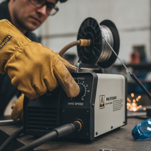
Wire feed speed (WFS) in flux core welding directly controls amperage. Unlike TIG or stick welding, where you set amps on a dial, MIG and flux core machines deliver current based on how fast the wire is consumed. Feed faster, and more wire enters the arc, drawing more current. Feed slower, and current drops.
This relationship means voltage and wire speed must be adjusted together. Voltage sets the arc length and width; wire speed sets the heat. Bump the wire speed without touching voltage and the arc becomes unstable. The result is usually excessive spatter, a convex bead, or erratic wire burn-back.
Flux Core Wire Speed Starting Ranges by Thickness
The table below gives practical starting ranges for self-shielded flux core wire (FCAW-S), which is the most common type used in home workshops, automotive repair, and farm fabrication. Dual-shield flux core wire used with external gas may require slightly different settings depending on the specific wire classification.
| Material Thickness | Wire Diameter | Voltage Range | Wire Feed Speed (IPM) |
|---|---|---|---|
| 18 gauge (1.2 mm) | 0.030″ | 13–15 V | 130–170 IPM |
| 16 gauge (1.6 mm) | 0.030″ | 14–16 V | 160–200 IPM |
| 3/16″ (4.8 mm) | 0.035″ | 16–18 V | 190–240 IPM |
| 1/4″ (6.4 mm) | 0.035″ | 17–19 V | 220–280 IPM |
| 3/8″ (9.5 mm) | 0.045″ | 18–21 V | 260–340 IPM |
| 1/2″ (12.7 mm) | 0.045″ | 19–22 V | 300–400 IPM |
These are approximate starting values for E71T-11 and similar self-shielded flux core wires on mild steel. Always confirm against your machine’s door chart and the wire manufacturer’s data sheet.
For a more detailed breakdown including dual-shield settings and material-specific guidance, the flux core MIG welding settings chart covers common weld scenarios across multiple wire sizes and joint types.
How to Read the Arc Sound When Dialing In Speed
The arc sound is the fastest feedback tool available. A properly dialed flux core arc produces a consistent crackling or frying sound — often compared to eggs sizzling in a pan. When wire speed is wrong, the sound changes noticeably:
- Too fast: Loud popping, sputtering, or machine-gun cracking. The wire is pushing into the puddle faster than it can melt.
- Too slow: Irregular sputtering, long arc flare, and frequent wire burn-back toward the contact tip. The wire is burning off before it reaches the puddle properly.
- About right: Steady, consistent crackle with minimal spatter landing on the base metal.
One variable that is often overlooked is contact tip-to-work distance (CTWD), also called stick-out. For flux core wire, the recommended stick-out is generally 3/4″ to 1″ (19–25 mm). Increasing stick-out beyond this range effectively reduces the current delivered to the weld, which can make a correctly set wire speed behave like it is running too fast relative to the actual heat at the arc.
Self-Shielded vs. Dual-Shield: Speed Settings Are Not Interchangeable
Self-shielded flux core wire (FCAW-S) and dual-shield flux core wire (FCAW-G) are fundamentally different products. Self-shielded wire generates its own protective atmosphere from the flux chemistry inside the wire. Dual-shield wire requires an external shielding gas — typically 75% Argon / 25% CO₂ — in addition to the flux core.
Wire speed ranges between these two types often differ because:
- Dual-shield wire generally runs at higher wire speeds and voltages for equivalent thickness
- Dual-shield wire produces cleaner welds with better mechanical properties, making it the preferred choice for structural and code work
- Self-shielded wire tolerates windier conditions and is more portable
If you switch wire types without adjusting your settings, the arc behavior will immediately reflect the mismatch. Running dual-shield settings on self-shielded wire typically results in an erratic, overdriven arc with excessive spatter.
Understanding the difference between flux core and standard MIG welding also helps clarify why flux core wire behaves differently from solid wire under the same voltage and speed settings.
Welding Position Changes the Equation
Flat position allows the most flexibility in wire speed. Gravity keeps the puddle where it belongs, which means you can run a slightly higher wire speed and maintain a flat, well-tied bead.
Vertical and overhead positions are more demanding. The puddle becomes harder to control at high heat, so reducing wire speed — and usually voltage alongside it — is standard practice. In vertical-up welding, a common starting adjustment is to reduce wire speed by roughly 10–15% from the flat-position baseline and then tune from there.
Overhead welding compounds these challenges further. A smaller, faster-moving puddle helps prevent metal from sagging, which usually means lower wire speed, tighter settings, and a shorter work cycle. The guide to overhead MIG welding covers technique adjustments that apply to flux core in that position as well.
Polarity for Flux Core Wire
Self-shielded flux core wire runs on DCEN (DC Electrode Negative), which is the opposite of solid MIG wire. This is a common source of confusion for welders who switch between solid wire and flux core on the same machine.
Running self-shielded flux core wire on DCEP (DC Electrode Positive) will produce a hot, erratic, excessively spatter-heavy arc that no amount of wire speed adjustment will fix. If the arc is consistently violent and messy despite correct settings, checking polarity should be the first diagnostic step — not adjusting the wire speed dial.
Dual-shield flux core wire typically runs on DCEP, matching standard solid MIG wire. Always confirm polarity against the wire manufacturer’s specification before making any settings adjustments. For a full explanation of how polarity affects MIG and flux core welding, the article on MIG welding polarity explains both DCEP and DCEN in practical terms.
Troubleshooting Common Wire Speed Problems
| Symptom | Likely Cause | What to Check | Practical Fix |
|---|---|---|---|
| Wire burns back to the tip | Speed too low | Confirm WFS setting and stick-out distance | Increase WFS incrementally, check CTWD |
| Excessive spatter, convex bead | Speed too high for voltage | Arc sound, bead profile | Lower WFS or increase voltage slightly |
| Cold, humped bead, poor fusion | Speed high, voltage low | Voltage setting | Increase voltage to match WFS |
| Irregular arc, popping | Wrong polarity | Polarity terminals | Switch to correct polarity for wire type |
| Porosity across the bead | Contamination or wind | Surface prep, stick-out, shielding | Clean base metal, increase stick-out, check for draughts |
| Wire bird-nesting at the drive roll | Feed resistance or tension | Drive roll tension, liner condition | Check liner for kinks, adjust roll tension |
Change one variable at a time. Adjusting wire speed and voltage simultaneously makes it harder to identify what actually resolved the issue.
When the Machine Chart Outranks Any Published Table
Every flux core wire behaves slightly differently depending on its exact classification, manufacturer formulation, and diameter. Published tables — including the one above — provide a starting point, not a guaranteed setting.
For machines like the Lincoln Electric Weld-Pak 140 HD or the Hobart Handler 140, the manufacturer’s door chart is calibrated specifically for that machine’s power output and wire drive system. A setting that works well on one machine may need minor adjustment on another, even at the same nominal output.
The same logic applies to wire manufacturer data sheets. Products like Lincoln Electric Innershield NR-211-MP, a commonly used self-shielded flux core wire, include recommended voltage and wire speed ranges in their product documentation. These specifications account for the wire’s specific flux chemistry and are more reliable than general internet tables for that exact product.
Safety Before Striking the Arc
Flux core welding produces substantial fume, particularly with self-shielded wire. The flux chemistry in FCAW-S wire creates a more aggressive fume profile than solid MIG wire with shielding gas. Ventilation is not optional.
Before welding:
- Wear a properly rated welding helmet — shade 10 is typically appropriate for most flux core work, though amperage affects the ideal shade
- Use flame-resistant clothing, leather welding gloves, and appropriate footwear
- Ensure adequate ventilation or local exhaust extraction
- Remove combustible materials from the welding area
- Confirm the work clamp is securely attached close to the weld zone
- Never weld galvanized, coated, or painted metal in an enclosed space without specific fume control
For galvanized or coated materials, the fume hazard increases significantly. Zinc oxide fumes from galvanized steel can cause metal fume fever. Grinding the coating back from the weld zone before welding is strongly recommended.
Frequently Asked Questions
What wire feed speed should I use for 1/4-inch steel with flux core wire?
For 0.035″ self-shielded flux core wire on 1/4-inch mild steel, a starting wire feed speed of roughly 220–280 IPM with 17–19 volts is a common starting range. Verify the setting against your machine’s door chart and the wire manufacturer’s data sheet before welding. Adjust in small increments based on arc sound and bead profile, and ensure polarity is set to DCEN for self-shielded wire.
Why does my flux core wire keep burning back to the tip?
Wire burn-back to the contact tip usually means the wire feed speed is too low relative to the voltage, or stick-out is too long. When the wire melts faster than it feeds, the arc climbs back up to the tip. Start by checking stick-out — it should be 3/4″ to 1″ for most flux core work — then increase wire speed incrementally. Also confirm the drive roll tension is adequate and the liner is not restricted.
Can I use the same wire speed for flux core as I do for solid MIG wire?
No. Flux core wire and solid MIG wire require different settings even at the same diameter. Flux core wire also changes polarity requirements — self-shielded wire runs DCEN, while solid MIG wire runs DCEP. Running the same wire speed without accounting for wire type, polarity, and the absence or presence of shielding gas will typically result in poor arc stability, spatter, and inconsistent penetration.
Does wire feed speed change for vertical welding with flux core?
Yes. Vertical welding requires reducing wire speed — and usually voltage — compared to flat position to keep the puddle small and manageable. A reduction of roughly 10–15% from the flat-position baseline is a common starting adjustment for vertical-up welding. Vertical-down welding uses different technique and may require further adjustment. Tune from there based on puddle behavior and bead profile.
What happens if I set the wire speed too high on thin material?
Running wire speed too high on thin gauge material — typically 16 gauge or thinner — produces excess heat that causes burn-through or warping. The wire feeds into the puddle faster than the metal can absorb the heat. Reduce wire speed and drop voltage together to maintain arc balance. On very thin sheet, running stitch or tack sequences rather than a continuous pass helps distribute heat and limit distortion.
How does stick-out affect my flux core wire speed settings?
Increasing stick-out beyond the recommended 3/4″ to 1″ range adds electrical resistance along the wire, which reduces current at the arc even if the machine setting hasn’t changed. This makes the arc behave as though the wire speed is too high relative to available heat. Shortening stick-out to the recommended range often resolves erratic arc behavior before any speed adjustment is necessary.
Is 0.030″ or 0.035″ flux core wire better for general repair work?
It depends on the material thickness. The 0.030″ wire handles lighter gauge material — typically 18 to 14 gauge — with better control and less risk of burn-through. The 0.035″ wire suits 3/16″ to 1/2″ material more efficiently and is the more common choice for general structural and farm repair work. Matching wire diameter to the primary material thickness you are welding reduces the amount of settings compensation required.
Getting the Setting Right the First Time
The most reliable approach is to start with your machine’s door chart or the wire manufacturer’s recommended range, set stick-out correctly, confirm polarity, and then listen to the arc. The sound tells you more than the dial does. Make one adjustment at a time — wire speed first, then voltage — until the arc crackles cleanly and the bead ties in flat at both edges without undercut or overlap.